audi Workshop Repair Guides

Audi Workshop Service and Repair Manuals

Removing and installing steering angle sender -G85- > < Removing and installing brake light sensor
Removing and installing ESP sensor unit -G419- / -G536-
  WARNING
The ESP sensor unit is sensitive to impact. Severe shocks or jolts can damage the ESP sensor unit. If the ESP sensor unit has been dropped by mistake it may not work properly and must not be installed in the vehicle.
  Note
The ESP sensor unit -G536- is not fitted on all models.
  Note
The ESP sensor unit -G419- and the ESP sensor unit -G536- are always located under the left-side seat.
Special tools and workshop equipment required
   
t  Torque wrench -V.A.G 1410-
Removing
  W00-0554
The ESP sensor unit -G419--1- and the ESP sensor unit -G536--3- are always located under the left-side seat.
The arrow on the sensor units points in the direction of travel.
–  Remove seat (left-side) → Rep. gr.72.
–  Fold up seam on carpet.
Use a sharp knife to cut through the carpet seam if this has not already been done.
–  Detach footwell vent.
  A45-10092
–  Unplug electrical connection -2- or -4-.
–  Remove securing nuts on sensor unit.
–  Lift out ESP sensor unit -G419--1- or ESP sensor unit -G536--3-.
Installing
  Note
The arrow on the sensor unit points in the direction of travel.
  WARNING
Severe shocks or jolts can irreparably damage the ESP sensor unit -G419-.
  A45-10092
–  Insert ESP sensor unit -G419--1- or ESP sensor unit -G536--3- into mounting from above.
When installing the ESP sensor units, make sure they are correctly seated in their mountings and are free of stress.
–  Install and tighten securing nuts on sensor unit.
  A45-10092
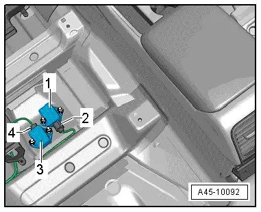
–  Plug in electrical connection -2- or -4-.
–  Install footwell vent.
–  Fold down seam on carpet.
–  Install seat (left-side) → Rep. gr.72.
After renewing the sensor unit, the following senders must be calibrated (basic setting):
t  Lateral acceleration sender -G200-
t  Longitudinal acceleration sender -G251-
Use vehicle diagnosis and service information system -VAS 5051B- or -VAS 5052- to do this.
–  Select on the display:
t  Running gear
t  Brake system
t  01 - Self-diagnosis compatible systems
t  03 - Brake electronics
–  Select required function on the display:
t  Calibrate lateral acceleration sender -G200-
t  Calibrate longitudinal acceleration sender -G251-
–  Then carry out ESP road test and system test.
  A45-10092

Removing and installing steering angle sender -G85- > < Removing and installing brake light sensor