
A4 Mk3
 Note
Note
|
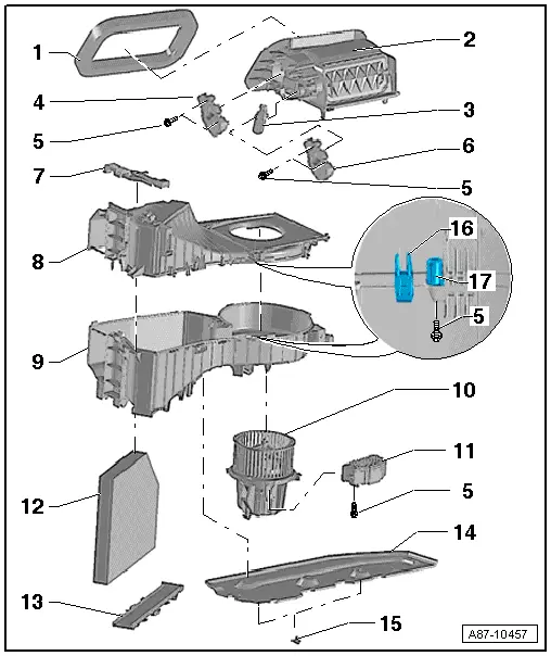
| 1 - | Foam seal |
| q | For sealing off fresh air intake housing from vehicle, bonded to air intake housing |
| 2 - | Air intake housing |
| q | With air flow, fresh-air and air recirculation flap |
| q | Not to be further dismantled |
| q | Detaching from air intake box/re-attaching → Chapter |
| 3 - | Cam plate |
| q | Actuates the air flow and fresh-air flap by way of two levers |
| q | Moisten the guides of the cam plate as well as the pins at the flap levers with a small quantity of grease e.g. lubricating paste -G 000 150- → Electronic parts catalogue. |
| 4 - | Air flow flap control motor -V71- |
| q | Removing and installing → Chapter |
| 5 - | Bolt |
| 6 - | Air recirculation flap control motor -V113- |
| q | Removing and installing → Chapter |
| 7 - | Catch |
| q | For fastening the air intake box to the air conditioning unit |
| 8 - | Top part of air intake box |
| q | Do not dismantle |
Note| t | Depending on the version of the genuine component, the top and bottom parts are bolted together at the attachment points or the top part is spot-welded to the bottom part. |
| t | The top and bottom parts of the air intake box are currently available as separate replacement parts. Assemble the two parts and then fasten them together with the bolts → Item at the attachment points provided → Item → Electronic parts catalogue. |
| q | If one of the retainer tabs → Item breaks off or one of the spot welds is no longer strong enough, the two parts of the housing can also be fastened together with bolts → Item. |
| q | Different versions (with and without connection for glove compartment cooling); this illustration shows the version with no connection for glove compartment cooling → Electronic parts catalogue |
| 9 - | Bottom part of air intake box |
| q | Do not dismantle |
Note| t | Depending on the version of the genuine component, the top and bottom parts are bolted together at the attachment points or the top part is spot-welded to the bottom part. |
| t | The top and bottom parts of the air intake box are currently available as separate replacement parts. Assemble the two parts and then fasten them together with the bolts → Item at the attachment points provided → Item → Electronic parts catalogue. |
| q | If one of the retainer tabs → Item breaks off or one of the spot welds is no longer strong enough, the two parts of the housing can also be fastened together with bolts → Item. |
| As of Model Year 2012 a modified version is gradually to be introduced. Pay attention to the notes on this component → Chapter „Components of air conditioning unit and air intake box with Basic type“ |
| 10 - | Fresh air blower -V2- |
| q | Removing and installing → Chapter |
| q | Checking → "Guided fault-finding" function of vehicle diagnostic, testing and information system VAS 5051 |
Note| t | As of 08.2007, fresh air blowers -V2- with an additional foam sheath at the housing (to reduce noise) are gradually being introduced → Chapter and → Electronic parts catalogue. |
| t | As of Model Year 2009, a fresh air blower -V2- with a modified housing (with optimised motor and adapted motor mount) is gradually being introduced. On introduction of the modified -V2-, the additional foam sheath at the housing is being discontinued. A modified insulating mat is however being installed on account of the larger motor mount → Item and → Electronic parts catalogue |
| t | In Model Year 2010, petrol engines designed for operation with bioethanol are being gradually introduced (Flex Fuel Vehicle). These engines are currently also fitted with a supplementary air heater element -Z35- → Chapter. |
| t | Vehicles with a high-voltage system (hybrid vehicles) and petrol engine are currently also fitted with a supplementary air heater element -Z35- → Chapter. |
| t | On vehicles with a petrol engine, the electric supplementary heating (supplementary air heater element -Z35-) is actuated by a signal from the operating and display unit, Climatronic control unit -J255- by way of the local data bus (via the same output by which the fresh air blower control unit -J126- is actuated) to the supplementary air heater control unit -J604-. In the event of problems with the fresh air blower control unit -J126- or the fresh air blower -V2- on these vehicles, also check the supplementary air heater control unit -J604- → "Guided fault-finding" function of vehicle diagnostic, testing and information system VAS 5051 and → Current flow diagrams, Electrical fault finding and Fitting locations. |
| t | Checking operation of supplementary air heater element -Z35- → Chapter. |
| t | As of Model Year 2012 and depending on the vehicle model, modified fresh air blower control units -J126-, fresh air blowers -V2-, air conditioner operating and display units, Climatronic control unit -J255- and air conditioning units are gradually to be introduced. Pay attention to the correct version and assignment of these components → Electronic parts catalogue and → "Guided fault-finding" function of vehicle diagnostic, testing and information system VAS 5051. |
| t | As of Model Year 2012 a modified version is gradually to be introduced. Pay attention to the notes on this component → Chapter „Components of air conditioning unit and air intake box with Basic type“ |
| 11 - | Fresh air blower control unit -J126- |
| q | Removing and installing → Chapter |
| q | Checking → "Guided fault-finding" function of vehicle diagnostic, testing and information system VAS 5051 |
Note| t | In Model Year 2010, petrol engines designed for operation with bioethanol are being gradually introduced (Flex Fuel Vehicle). These engines are currently also fitted with a supplementary air heater element -Z35- → Chapter. |
| t | Vehicles with a high-voltage system (hybrid vehicles) and petrol engine are currently also fitted with a supplementary air heater element -Z35- → Chapter. |
| t | On vehicles with a petrol engine, the electric supplementary heating (supplementary air heater element -Z35-) is actuated by a signal from the operating and display unit, Climatronic control unit -J255- by way of the local data bus (via the same output by which the fresh air blower control unit -J126- is actuated) to the supplementary air heater control unit -J604-. In the event of problems with the fresh air blower control unit -J126- or the fresh air blower -V2- on these vehicles, also check the supplementary air heater control unit -J604- → "Guided fault-finding" function of vehicle diagnostic, testing and information system VAS 5051 and → Current flow diagrams, Electrical fault finding and Fitting locations. |
| t | Checking operation of supplementary air heater element -Z35- → Chapter. |
| t | As of Model Year 2012 (introduction depending on vehicle model) modified fresh air blower control units -J126- (and fresh air blowers -V2-, air conditioner operating and display units, Climatronic control unit -J255- and air conditioning units with part number „8T_ 820 005“) are gradually being introduced. The air intake box has been modified together with -J126- and the air conditioning unit. Pay attention to the correct version and mutual assignment of these components → Electronic parts catalogue and → "Guided fault-finding" function of vehicle diagnostic, testing and information system VAS 5051. |
| t | As of Model Year 2012 a modified version is gradually to be introduced. Pay attention to the notes on this component → Chapter „Components of air conditioning unit and air intake box with Basic type“ |
| 12 - | Dust and pollen filter |
| q | Removing and installing → Chapter |
| q | Heed replacement intervals → Maintenance tables |
| q | Different versions with and without activated charcoal filter element → Chapter |
| 13 - | Dust and pollen filter cover |
| q | Removing and installing → Chapter |
| 14 - | Insulating mat |
| q | Removing and installing → Chapter |
| q | Different versions depending on design of fresh air blower -V2- → Item and → Electronic parts catalogue |
| 15 - | Screw-type clip |
| 16 - | Fasteners at top part of air intake box |
| 17 - | Attachment point |