audi Workshop Repair Guides

Audi Workshop Service and Repair Manuals

Removing and installing air conditioner compressor (vehicles with 8-cyl. FSI engine) > < Removing and installing air conditioner compressor (vehicles with 6-cyl. TDI engine)
Removing and installing air conditioner compressor (vehicles with 6-cyl. petrol engine)
Removing
–  Switch off the ignition.
–  Drain the refrigerant circuit → Air conditioner with refrigerant R134a.
  Note
t  Depending on the position of the service connection at the refrigerant line and the vehicle model, it may be necessary to remove the additional body brace stiffener on the left to permit connection of the service coupling of the air conditioner service station (e.g. on the Audi Q5) → Running gear; Rep. gr.40 and → Air conditioner with refrigerant R134a
t  As opposed to other vehicles, removal of the air conditioner compressor on the Audi RS 5 does not involve unfastening the coolant expansion tank, but rather taking out the left air cleaner → Engine, mechanics; Rep. gr.14
   
–  Detach the coolant hose -3- from the coolant expansion tank → Engine, mechanics; Rep. gr.13 (not Audi RS 5).
–  Screw out the bolts -arrows- and lay aside the coolant expansion tank with the coolant hoses -1- and -2- connected → Engine, mechanics; Rep. gr.19 (not Audi RS 5).
–  Completely remove the left air cleaner → Engine, mechanics; Rep. gr.24 (Audi RS 5 only).
–  Remove the front noise insulation → General body repairs, exterior; Rep. gr.50.
  A10-10850
–  Screw out the bolts -1-, unscrew the nuts -3- and detach the left longitudinal member -2- → General body repairs, exterior; Rep. gr.50.
–  Remove the front left wheel and the front left wheel housing liner → General body repairs, exterior; Rep. gr.50.
  A10-10844
–  Mark the direction of the poly V-belt -A- → Engine, mechanics; Rep. gr.13.
–  Detach the poly V-belt -A- → Engine, mechanics; Rep. gr.13.
–  If fitted, pinch off the supply pipe to the power steering vane pump -B- with hose clamps up to 25 mm -3094- → Running gear; Rep. gr.48.
–  If necessary, detach the pressure pipe -C- to the power steering vane pump -B- → Running gear; Rep. gr.48.
  Note
t  When swivelling aside the pressure pipe, take care not to bend, kink or strain the pipe to the vane pump.
t  Removal of the air conditioner compressor does not involve unfastening the power steering vane pump -B- from the holder.
t  The pressure pipe and vane pump are only fitted on vehicles without electromechanical power steering → Running gear; Rep. gr.48.
  A87-10577
t  The pressure pipe to the vane pump -C- (refer to top illustration) is attached by way of the holder to the air conditioner compressor with the bolt -C- (refer to bottom illustration).
–  Detaching refrigerant lines from air conditioner compressor → Chapter.
  Note
The refrigerant lines are detached from above.
  A87-10578
–  Unplug the connector -A-.
–  Remove the bolt -B- (and bolt -C-) (tightening torque 25 Nm).
  Note
t  On vehicles with a vane pump, the bolt -C- (tightening torque 25 Nm) is already removed on unfastening the pressure pipe to the vane pump.
t  The pressure pipe and vane pump are only fitted on vehicles without electromechanical power steering → Running gear; Rep. gr.48.
t  This illustration shows the air conditioner compressor in a vehicle with a continued coolant circulation pump -V51- (not fitted on all models). Depending on the rest of the vehicle equipment, it may be necessary to drain the coolant and take out -V51- to permit removal of the air conditioner compressor (for coolant drainage and removal of -V51-, refer to → Engine, mechanics; Rep. gr.19).
t  Depending on the version of the air conditioner compressor and the vehicle model (different radiator fans, radiators and tubing to -V51-), it may also be necessary to move the lock carrier to service position (to enable the air conditioner compressor to be swivelled out downwards) → General body repairs, exterior; Rep. gr.50.
Notes on lock carrier service position:
  A87-10578
t  Removing the bolts -A- first and, following removal of the bolts -A-, marking the position of the lock carrier -B- (through the hole on the left and right) at the longitudinal member -C- with water-proof ink for example permits re-installation at exactly the same location.
t  Removal of the two bolts -D- and insertion of longer bolts -E- instead (e.g. M10 x 100 bolts) makes it possible to pull the lock carrier forwards by approx. 60 mm after removing the bolts -F-.
t  The sleeves -G- (or a suitable block with a side length of approx. 60 mm) can be used to secure the lock carrier -C- to stop it sliding back.
  A87-10576
–  Detach the holder -D-.
–  Remove the bolt -E- (tightening torque 25 Nm).
–  Unfasten the air conditioner compressor -F- from the holder, pull forwards and swivel out downwards.
Installing
Install in reverse order, paying attention to the following:
  Note
The air conditioner compressor removed contains an indeterminate amount of refrigeration oil. Attention is therefore to be paid to the notes on air conditioner compressor replacement. → Air conditioner with refrigerant R134a
Before fitting the air conditioner compressor → Air conditioner with refrigerant R134a:
  A87-10578
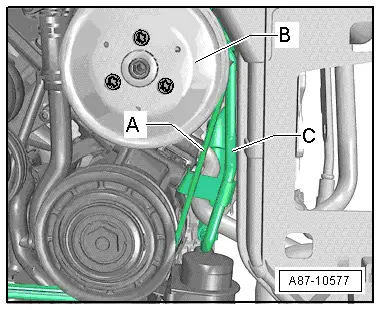
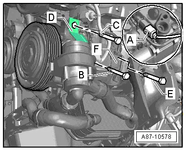
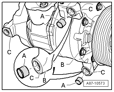
–  Before securing the air conditioner compressor, check the position of both dowel sleeves -A- in the holder or air conditioner compressor -B-.
  Note
t  There are different versions of the dowel sleeves -A- (different length). Attention is therefore to be paid to the correct version → Electronic parts catalogue.
t  Pay attention to correct positioning of the bushings -A- as well as to clean contact surfaces. Incorrectly fitted bushings or dirty/damaged contact surfaces -C- at the holder or air conditioner compressor could lead to misalignment between the air conditioner compressor and engine. In the course of operation, misalignment may result in poly V-belt or air conditioner compressor damage.
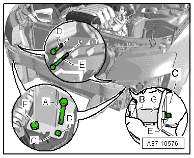
–  Crank the air conditioner compressor 10 times by way of the pulley in the direction of rotation before fitting the poly V-belt (to prevent compressor damage on initial activation).
–  Fit the pressure pipe to the power steering vane pump → Running gear; Rep. gr.48.
–  Fit the poly V-belt -A- → Engine, mechanics; Rep. gr.13.
–  Attach the refrigerant lines to the air conditioner compressor → Chapter.
  Note
t  Moisten the O-rings slightly with refrigeration oil before fitting → Chapter.
t  Cranking prevents air conditioner compressor damage which could be caused by refrigeration oil in the compression chamber on initial start-up of the engine.
t  After attaching the air conditioner compressor and the refrigerant line, check the routing of the refrigerant lines. They must be inserted in the holders provided (if fitted, depends on engine).
t  Check the refrigerant lines and the corresponding holders for adequate clearance with respect to the other components, ensuring a sufficient distance between the belt, holder and pulley.
–  Evacuate and charge the refrigerant circuit → Air conditioner with refrigerant R134a.
–  Re-install the remaining components removed.
–  Interrogate the event recorder of the operating and display unit, Climatronic control unit -J255- and erase any faults displayed → "Guided fault-finding" function of vehicle diagnostic, testing and information system VAS 5051.
–  Start up the air conditioner after charging the refrigerant circuit → Chapter.
  Note
Also heed the notes on start-up of the air conditioner after charging → Air conditioner with refrigerant R134a.
  A87-10573

Removing and installing air conditioner compressor (vehicles with 8-cyl. FSI engine) > < Removing and installing air conditioner compressor (vehicles with 6-cyl. TDI engine)