| –
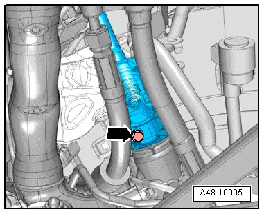
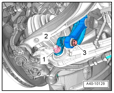
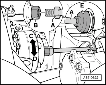
| To avoid compressor damage on initial activation, give the air conditioner compressor drive unit -B- 10 turns by hand in -direction of arrow C- at the air conditioner compressor before screwing in the air conditioner compressor drive shaft -A-. |

Note | Any refrigeration oil which has collected in the air conditioner compressor removed or in the compression chamber of the air conditioner compressor after pouring in fresh refrigeration oil (e.g. after blowing out the refrigerant circuit) is forced out of the compression chamber by the cranking action. |
| –
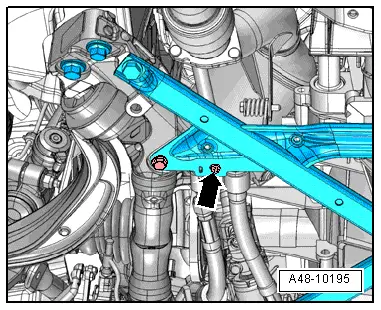
| Hold the air conditioner compressor drive shaft -A- with an open-ended spanner and turn the air conditioner compressor drive unit -B- in -direction of arrow D-. |
| l
| Tightening torque: 60 Nm |
Note | t
| Do not turn the air conditioner compressor drive shaft -A- when tightening. |
| t
| After fitting, check the installation position of the socket -E- on the drive gear. |
| t
| After fitting the drive shaft -A-, check the installation position of the socket -E-. |
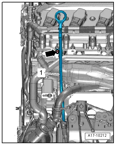
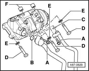
Note | Replace the seal, the self-locking nuts and the O-ring for the dipstick guide tube. |
| –
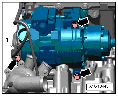
| Re-install the remaining components removed. |
| –
| Start up the air conditioner after charging the refrigerant circuit → Chapter. |
Note |
|
|

 Caution