audi Workshop Repair Guides

Audi Workshop Service and Repair Manuals

Removing and installing clutch for four-wheel driveN445 or clutch valve 2 for four-wheel driveN446 > < Removing and installing four-wheel drive pumpV415
Removing and installing oil pressure and oil temperature senderG437 or oil pressure and oil temperature sender 2G640
Removing and installing oil pressure and oil temperature sender -G437- or oil pressure and oil temperature sender 2 -G640-
Special tools and workshop equipment required
   
t  Bit (27 mm) -T40218-
  W00-10779
t  
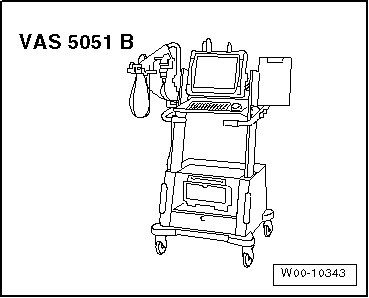
Vehicle diagnostic, testing and information system -VAS 5051-
Important safety precautions:
t  After renewing the oil pressure and oil temperature sender -G437- or the oil pressure and oil temperature sender 2 -G640-, the identity of the corresponding sender must be re-adapted in the four-wheel drive control unit -J492- → Vehicle diagnostic, testing and information system VAS 5051.
t  
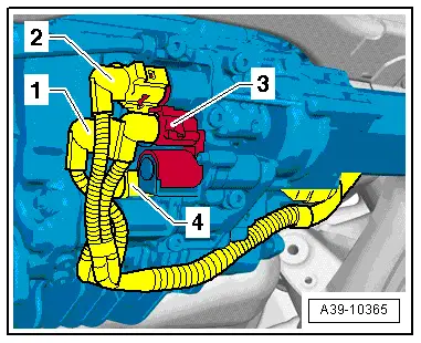
Do not renew both oil pressure and oil temperature senders (-G437- and -G640-) at the same time, as at least one valid sender identity is required at any time for the allocation of the rear final drive to the four-wheel drive control unit -J492-. If both senders are renewed at the same time, the four-wheel drive control unit -J492- would interpret this as the replacement of the rear final drive. This would erase all the learnt values in the control unit and impair the performance of the rear final drive.
t  If both oil pressure and oil temperature senders (-G437- and -G640-) have to be renewed due to mechanical damage, e.g. damage to the connector housing, this should be done in two steps: After the first sender has been renewed, the identity of the sender must be re-adapted in the four-wheel drive control unit -J492- → Vehicle diagnostic, testing and information system VAS 5051. Proceed in the same manner for the second sender.
t  If both oil pressure and oil temperature senders (-G437- and -G640- have to be renewed due to an electrical fault, the clutch classification must be entered again in the four-wheel drive control unit -J492- → Vehicle diagnostic, testing and information system VAS 5051. In addition, the ATF in the rear final drive must be renewed → Chapter.
  Note
t  Refer to general repair instructions → Chapter.
t  Observe safety precautions → Chapter.
Removing
l  Ignition is switched off.
–  Place vehicle on lifting platform.
–  Lower rear section of exhaust system slightly and secure.
–  If necessary, remove bracket for wiring harness from rear final drive → Anchor.
  W00-10343
–  Unplug connector -1- from oil pressure and oil temperature sender 2 -G640- / connector -2- from oil pressure and oil temperature sender -G437-.
  Note
If necessary, unplug connectors -3- and -4-.
–  Position drip tray under rear final drive.
  A39-10365
–  Remove corresponding sender using bit -T40218-.
   -A- = oil pressure and oil temperature sender 2 -G640- - black connection
   -B- = oil pressure and oil temperature sender -G437- - brown connection
  A39-10372
Installing
–  Carefully screw in new sender with new O-ring -arrow- at its fitting location and tighten to specified torque → Item or → Item.
   -A- = oil pressure and oil temperature sender 2 -G640- - black connection
   -B- = oil pressure and oil temperature sender -G437- - brown connection
  A39-10372
–  Plug in connector -1- at oil pressure and oil temperature sender 2 -G640- / connector -2- at oil pressure and oil temperature sender -G437-.
  Note
If unplugged earlier, plug in connectors -3- and -4-.
–  If removed earlier, install bracket for wiring harness at rear final drive → Anchor.
–  Connect vehicle diagnostic, testing and information system -VAS 5051- and switch on ignition.
–  Using vehicle diagnostic, testing and information system -VAS 5051- in Guided Functions mode, select 22 - Four-wheel electronics and then select the function 22 - Adapting sender.
l  It is important to follow all instructions given by the vehicle diagnostic, testing and information system -VAS 5051- exactly.
Using vehicle diagnostic, testing and information system -VAS 5051B-, „adapt“ new sender to four-wheel drive control unit -J492-.
  Note
When 22 - Adapting sender function has been completed, a system check is performed. Any malfunctions during this test must be eliminated via the „Guided Fault Finding“.
–  Top up ATF in rear final drive → Chapter.
–  Secure rear section of exhaust system to body and align so it is free of stress → Rep. gr.26.
  A39-10365

Removing and installing clutch for four-wheel driveN445 or clutch valve 2 for four-wheel driveN446 > < Removing and installing four-wheel drive pumpV415