audi Workshop Repair Guides

Audi Workshop Service and Repair Manuals

Checking torque distribution > < Removing and installing oil pressure and oil temperature senderG437 or oil pressure and oil temperature sender 2G640
Removing and installing clutch for four-wheel driveN445 or clutch valve 2 for four-wheel driveN446
Removing and installing clutch for four-wheel drive -N445- or clutch valve 2 for four-wheel drive -N446-
Special tools and workshop equipment required
   
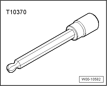
t  Socket (4 mm) -T10370-
  Note
t  Refer to general repair instructions → Chapter.
t  Observe safety precautions → Chapter.
  Caution
Malfunctions on rear final drive.
Do NOT interchange fitting location of clutch valve for four-wheel drive -N445- with fitting location of clutch valve 2 for four-wheel drive -N446-.
Removing
l  Ignition is switched off.
–  Place vehicle on lifting platform.
–  Lower rear section of exhaust system slightly and secure.
–  Remove bracket for wiring harness from rear final drive → Anchor.
  Note
  W00-10582
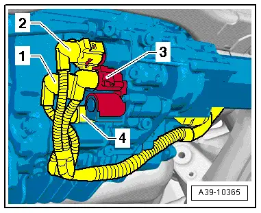
t  Mark connectors -1 ... 4- for oil pressure and oil temperature senders and clutch valves.
t  Unplug connectors -1- and -2-.
–  Unplug connector -3- from clutch valve 2 for four-wheel drive -N446- / connector -4- from clutch valve for four-wheel drive -N445-.
–  Position drip tray under rear final drive.
  A39-10365
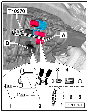
–  Unscrew bolts -1- of corresponding clutch valve using 4 mm socket -T10370-
–  Carefully prise out clutch valve e.g. using a flat screwdriver; observe spring -3-. Spring can fall out of opening in hydraulic control unit -6-.
   -A- = clutch valve 2 for four-wheel drive -N446-, brown colour coding
   -B- = clutch valve for four-wheel drive -N445-, black colour coding
  A39-10373
Installing
l  Ball -5-, guide -4- (small diameter facing spring) and spring -3- must be installed in opening in housing -6- for clutch valve-2-.
–  Install new clutch valve with new O-rings -arrows- (coat O-rings with ATF).
–  Pre-tighten bolts -1- evenly hand-tight until they make contact. Then tighten to specified torque → Item.
Perform remaining installation operations in reverse order of removal. Note the following:
  Note
  A39-10373
t  Allocation of connectors for oil pressure and oil temperature senders and at clutch valves:
t  -1- = connector for oil pressure and oil temperature sender 2 -G640-
t  -2- = connector for oil pressure and oil temperature sender -G437-
t  -3- = connector for clutch valve 2 for four-wheel drive -N446-
t  -4- = connector for clutch valve for four-wheel drive -N445-
–  Attach bracket for wiring harness to rear final drive → Anchor.
–  Top up ATF in rear final drive → Chapter.
–  Secure rear section of exhaust system to body and align so it is free of stress → Rep. gr.26.
  A39-10365

Checking torque distribution > < Removing and installing oil pressure and oil temperature senderG437 or oil pressure and oil temperature sender 2G640