
A4 Mk3
| Removing timing chains from camshafts |
| Special tools and workshop equipment required |
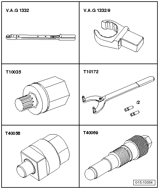
| t | Torque wrench -V.A.G 1332- |
| t | Socket -V.A.G 1332/9- |
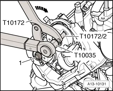
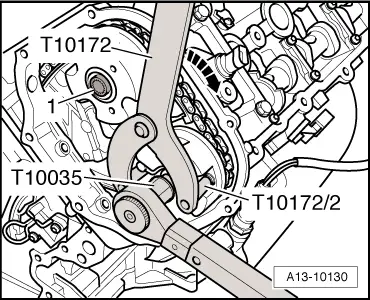
| t | Special wrench -T10035- |
| t | Counterhold tool -T10172- |
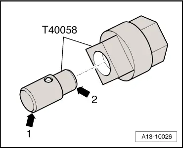
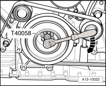
| t | Adapter -T40058- |
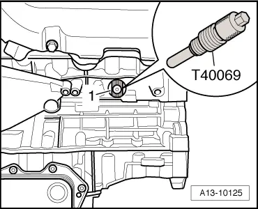
| t | Locking pin -T40069- |
|
|
|
|
|
|
|
|
 Note
Note
|
|
|
|
|
|
|
|
|
|
Note |
|
|
|
|
|
|
|
Note
|
|
Note
|
|
Note
|
|
|
|
 Caution
|
|
Note
|
|
|
|
Note
|
|
Note |
|
Note |
|
|
|
|
|
|
|
|
|
Note
|
|
|
|
|
|
|
|
|
|
Note
|
|
|
|
|
|
|
|