
A5
| Removing gearbox – vehicles with 4-cylinder diesel engine |
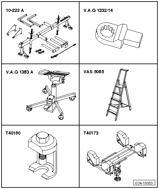
| Special tools and workshop equipment required |
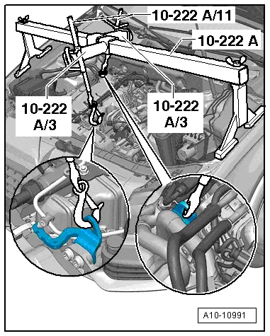
| t | Support bracket -10 - 222 A- |
| t | Ring spanner insert, 16 mm -V.A.G 1332/14- |
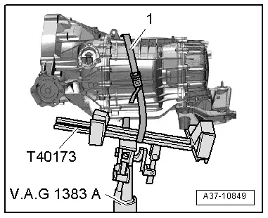
| t | Engine and gearbox jack -V.A.G 1383 A- |
| t | Stepladder -VAS 5085- |
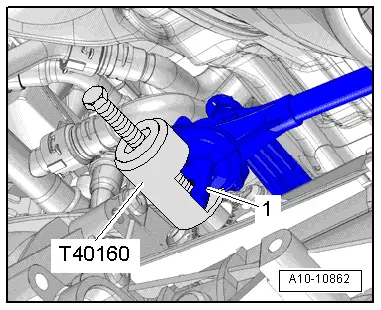
| t | Puller -T40160- |
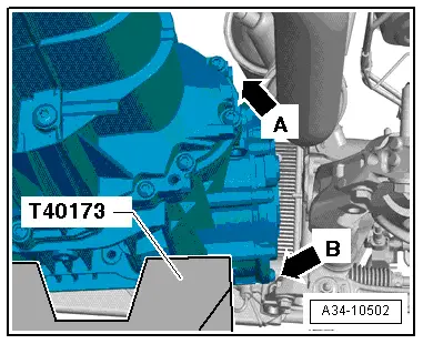
| t | Gearbox support -T40173- |
|
|
|
|
|
|
 Caution
|
|
|
|
|
|
|
|
|
|
|
|
|
|
 WARNING
|
|
|
|
|
|
 Note
Note
|
|
Note
|
|
|
|
Note
|
|
|
|
|
|
|
|
|
|
|
|
|
|
|
|
|
|
|
|
Note
|
|
|
|
|
|
|
|
|
|
Note
|
|
Note
|
|
|
|
Note
|
|
|
|
Note
|
|
Note
|
|
|
|
Note
|
|
|
|
|
|