
A5
|
|
|
|
|
 Note
Note
|
|
Note
|
|
Note
|
|
Note
|
|
|
|
|
|
Note
|
|
|
|
Note
|
|
 Caution
Note
|
|
|
|
|
|
|
|
Note |
|
|
|
Note
|
|
|
|
|
|
Note
|

|
Note
|
|
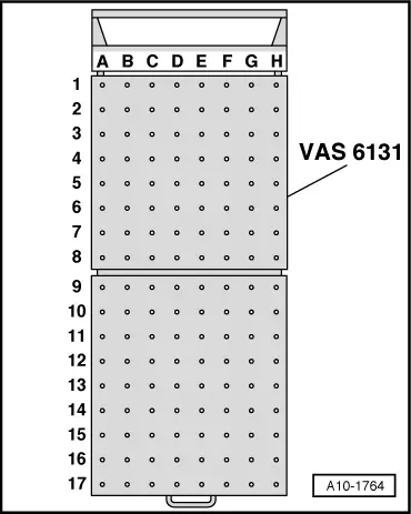
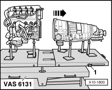
| Platform coordinates | Parts of support set for Audi -VAS 6131/10-, supplementary set -VAS 6131/13- and gearbox support -VAS 6131/14- | |||
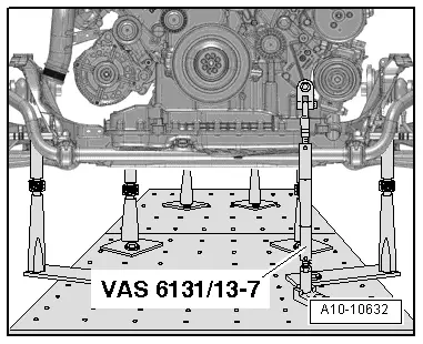
| D2 | /13-7 | |||
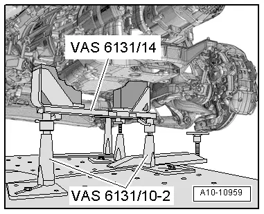
| B10 | /10-1 | /10-2 | /10-5 | /14 |
| G10 | /10-1 | /10-2 | /10-5 | |
|
|
|
|
Note
|
|
|
|