audi Workshop Repair Guides

Audi Workshop Service and Repair Manuals

Assembly mountings > < Removing and installing engine - vehicles with automatic gearbox 0B6
Installing engine
Installing engine
Special tools and workshop equipment required
   
t  Ring spanner insert AF 16 -V.A.G 1332/14-
  W00-1329
t  Assembly aid -T40169-
  W00-10593
t  Transport lock -T40170-
Tightening torques
  Note
t  Tightening torques apply only to lightly greased, oiled, phosphated or black-finished nuts and bolts.
t  Additional lubricants such as engine or gearbox oil may be used, but do not use lubricants containing graphite.
t  Do not use de-greased parts.
t  Tolerance for tightening torques: ± 15 %.
  W00-10594
ComponentNm
Bolts/nutsM69
M715
M820
M1040
M1265

Assembly mountings → Chapter.
   
Earth stud at suspension turret - tightening torque
–  Tighten earth stud -1- to 9 Nm.
  A10-10856
Earth wiring at longitudinal member - tightening torque
–  Tighten nut -arrow- to 9 Nm.
  A10-10843
Engine to dual-clutch gearbox 0B5
  A34-10370
ItemBoltNm
1M10x50 1)65
2 … 6M12x100 2)30 + 90°
7M12x125 2)30 + 90°
8, 11M10x60 2)15 + 90°
9, 10M10x95 2)15 + 90°
ADowel sleeves for centralising
l  1) Property class 10.9. The steel bolt may be re-used as often as necessary.
l  2) Aluminium bolts must not be used more often than twice → Anchor.

   
t  
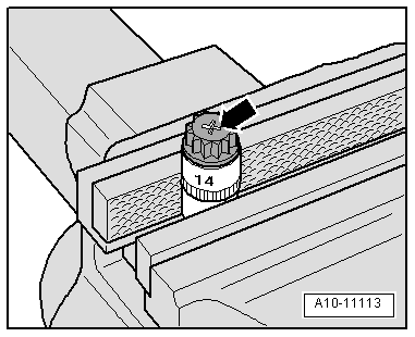
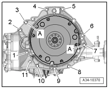
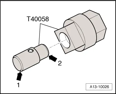
The aluminium bolts -2 … 11- must not be used more often than twice. After the first use, the bolts must therefore be identified with an „X“ made by two chisel marks -arrow-.
t  
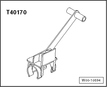
To avoid damaging the bolts when making this mark, do not clamp them directly in a vice. Clamp a 14 mm socket with 1/2" drive in a vice and insert the bolt as shown.
t  Bolts already marked with an „X“ must not be used again.
Procedure
  Note
t  Renew the bolts tightened with specified tightening angle.
t  
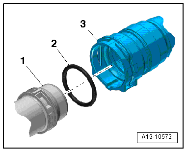
Renew self-locking nuts and bolts as well as seals, gaskets and O-rings.
t  
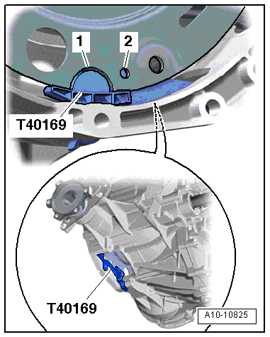
On vehicles with dual clutch gearbox 0B5, a needle bearing is fitted in the drive plate. Before installing, check that the needle bearing is fitted. Removing and installing needle bearing in drive plate (pressing in and out) → Chapter.
t  Hose connections and air pipes and hoses must be free of oil and grease before assembly.
t  Secure all hose connections with the correct type of hose clips (same as original equipment) → Electronic parts catalogue.
t  To ensure that the air hoses can be properly secured at their connections, spray rust remover onto the worm thread of used hose clips before installing.
t  Fit all cable ties in the original positions when installing.
–  Install engine supports and engine mountings → Chapter.
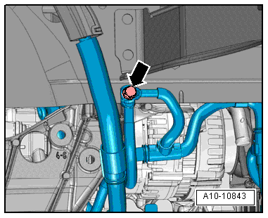
–  Install coolant pipe (bottom right) → Chapter.
–  Hold ATF lines in installation position when joining engine and subframe.
–  Before installing gearbox, remove residue from threaded holes for engine/gearbox bolts in cylinder block using a thread tap.
  A10-11113
–  The following preparations are required before joining engine and gearbox.
–  Insert assembly aid -T40169- into gearbox housing and dual-mass flywheel from below, as illustrated.
l  The assembly aid must engage in the semi-circular recess -1- and in the inspection hole -2-.
  Note
There is only one inspection hole on the circumference; turn the dual-mass flywheel accordingly.
–  Insert pin of assembly aid into hole on gearbox housing.
  A10-10825
–  Insert transport lock -T40170- into gearbox housing from below and clamp onto flange shaft -1-.
  A10-10826
–  Check whether dowel sleeves -A- for centring engine and gearbox are fitted in cylinder block; install missing dowel sleeves.
–  Check whether aluminium bolts securing engine to gearbox can be reused; if so, apply marking → Anchor.
–  Bring gearbox into position on engine and tighten bolts -1 … 11-.
–  Remove transport lock -T40170- and assembly aid -T40169-.
  Note
  A34-10370
The following step is necessary to ensure that the clutch module is straight and that it makes even contact with the drive plate.
–  Using assembly lever -1-, press clutch module -2- slightly against drive plate -3--arrow-.
  A34-10497
–  Bolt clutch module onto drive plate as follows:
  Note
Use ring spanner insert AF 16 -V.A.G 1332/14- to tighten bolts.
–  Hand-tighten first bolt -arrow- (2 Nm).
  A10-10629
–  Insert guide pin of adapter -T40058- as follows:
l  The larger-diameter section -arrow 1- faces towards the engine.
l  The smaller-diameter section -arrow 2- faces the adapter.
  A13-10026
–  Turn crankshaft 180° further in normal direction of engine rotation -arrow- with adapter -T40058-.
–  Tighten bolt accessible in this crankshaft position to specified torque → Rep. gr.34.
–  Turn crankshaft by 60° each time and tighten remaining 5 bolts to specified torque → Rep. gr.34.
–  Install hydraulic fluid lines for power steering → Rep. gr.48.
–  Install poly V-belt tensioner → Chapter.
–  Bolt drive shafts (left and right) onto gearbox flange shafts → Rep. gr.40.
–  Install ATF lines → Rep. gr.34.
–  Install particulate filter → Chapter.
–  Install heat shield for turbocharger → Chapter.
–  Raise engine/gearbox assembly using scissor-type assembly platform -VAS 6131 A-.
–  Align subframe and tunnel cross member on longitudinal members according to markings made before removal.
  A13-10022
–  Tighten subframe bolts only to specified torque (do not turn further); the bolts are only to be fully tightened after performing the wheel alignment check → Rep. gr.40.
  WARNING
Risk of accident because of loose bolt connections.
Do NOT drive the vehicle unless the subframe bolts have been finally tightened.
  A10-10868
–  Tighten bolts for tunnel cross member → Rep. gr.34.
Remaining installation steps are carried out in reverse sequence; note the following:
–  Install propshaft → Rear final drive 0BC; Rep. gr.39 or → Rear final drive 0BD; Rep. gr.39.
–  Install front exhaust pipe → Chapter.
–  Align the exhaust system so it is free of stress → Chapter.
–  Install front cross member → Rep. gr.66.
–  Install selector lever cable → Rep. gr.34.
–  Secure universal joint on steering box → Rep. gr.48.
–  Install subframe cross brace, upper suspension links and anti-roll bar; secure suspension strut to track control link → Rep. gr.40.
–  Install brake calipers → Rep. gr.46.
–  Install struts for lock carrier → Rep. gr.50.
–  Install engine control unit → Rep. gr.23.
–  Electrical connections and routing → Current flow diagrams, Electrical fault finding and Fitting locations.
–  Install electrical wiring, terminal 30 wiring junction 2 -TV22- and cover for electronics box in engine compartment → Fig., → Fig. and → Rep. gr.97.
–  Plug in electrical connectors for exhaust gas temperature senders → Chapter.
–  Install body brace → Rep. gr.40.
–  Install filler neck for washer fluid reservoir → Electrical system; Rep. gr.92.
–  Install refrigerant lines → Rep. gr.87.
–  Observe notes on procedure for connecting the battery → Electrical system; Rep. gr.27.
  Caution
Risk of irreparable damage to control units because of excessive voltage.
Never use battery charging equipment for boost starting.
–  Install throttle valve module -J338-, exhaust gas pressure sensor 1 -G450- and air cleaner housing → Rep. gr.23.
–  Fill up with engine oil and check oil level → Booklet811, → Booklet812 or → Booklet818.
–  Before starting engine, top up hydraulic fluid in power steering reservoir → Rep. gr.48.
  Note
The power steering pump must not be run when dry.
  A10-10866
–  Connect coolant hose and connection with plug-in connector → Fig..
–  Fill up with coolant → Anchor.
  Note
t  Do not use drained coolant again if:
t  the cylinder head or cylinder block have been renewed.
t  the coolant is contaminated or dirty.
–  Charge refrigerant system → Air conditioner with refrigerant R134a.
–  Install wheel housing liners → Rep. gr.66.
–  Fit front wheels and perform wheel alignment → Rep. gr.44.
  WARNING
Risk of accident because of loose bolt connections.
Tighten subframe bolts to final setting after performing wheel alignment check.
–  Fill up with ATF → Rep. gr.34.
–  Install noise insulation panels → Rep. gr.66.
  A19-10572

Assembly mountings > < Removing and installing engine - vehicles with automatic gearbox 0B6