
Skylark V6-3100 3.1L VIN M SFI (1996)
Brake Master Cylinder: Service and Repair
Hydraulic Modulator
CAUTION: To help avoid personal injury, due to a retained load on the ABS hydraulic modulator, the gear tension relief function of the Tech
1 must be performed prior to removal of the ABS hydraulic modulator/master cylinder assembly. Refer to "Gear Tension Relief Sequence".
NOTICE: Complete overhaul of the hydraulic modulator/master cylinder assembly is not authorized, only the following steps. These steps will break the
unit down into major components for replacement purposes.
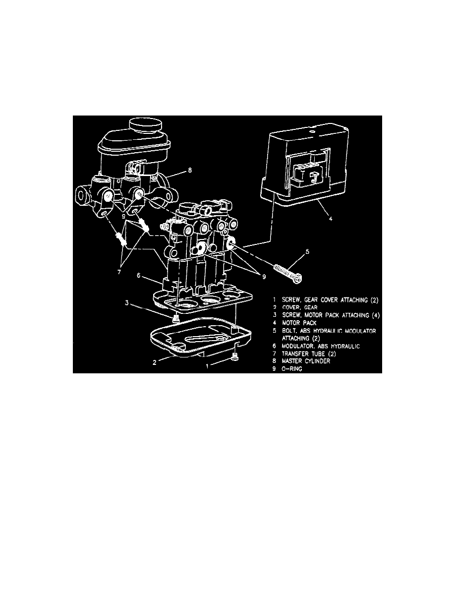
HYDRAULIC MODULATOR
Hydraulic Modulator/Master Cylinder Assembly
DISASSEMBLE
1. Hydraulic modulator/master cylinder assembly.
2. Torx head screws attaching gear cover.
3. Remove gear cover.
4. Four Torx head screws attaching motor pack to hydraulic modulator.
5. Remove motor pack.
6. Two hydraulic modulator to master cylinder banjo bolts, separate hydraulic modulator from master cylinder.
7. Two transfer tubes with 0-rings from master cylinder or hydraulic modulator.
8. Banjo bolt 0-rings from master cylinder and hydraulic modulator.
IMPORTANT:
^
If hydraulic modulator is to be replaced, install the three gears in the same location on replacement hydraulic modulator. Refer to "Gear
Replacement".
^
No repair of the hydraulic modulator is authorized. Replace as an assembly.
^
Use new transfer tube assemblies when assembling the hydraulic modulator/master cylinder assembly. Make sure two 0-rings are properly installed
on each transfer tube.
ASSEMBLE
1. Two transfer assemblies.
^
Lubricate transfer tube assembly 0-rings with clean brake fluid.