
DeVille V8-252 4.1L VIN 8 FI (1983)
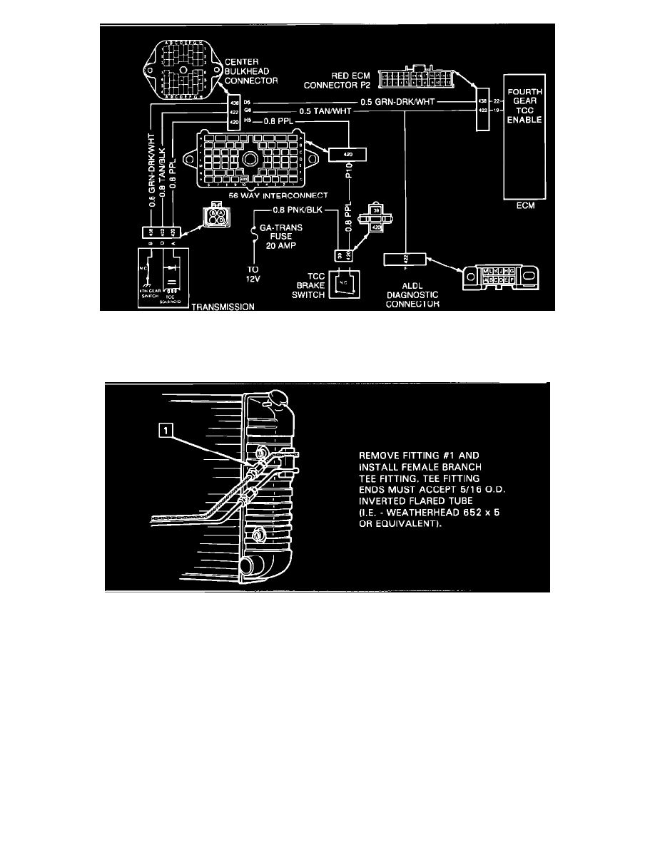
FIGURE 6 - DFI TRANSMISSION CIRCUIT
On Figure 6, DFI Transmission Circuit, the center bulkhead connector shown is for 1984 vehicles only. For location of terminals and connector
illustration on 1982 or 1983 vehicles, refer to the appropriate model year Service Information Manual.
FIGURE 7 - TEE FITTING INSTALLATION
Refer to Figure 7 for illustration of Tee Fitting for hydraulic diagnosis.
NOTE ON INTERMITTENTS: If the electrical and hydraulic test procedures did not define the cause of the code 39, an intermittent electrical or
hydraulic condition could exist.
ELECTRICAL INTERMITTENTS:Could be due to the adjustment of the brake switches. The ECM does not test for the TCC code if it sees the brake
applied through the Cruise Control brake signal on circuit #86. This is because the TCC brake switch is also open
under this condition. If the TCC brake switch is adjusted such that it opens before the Cruise Control brake release
switch, a code 39 could be set if the operator were to keep the brake pedal applied just enough to open the TCC
switch but not the Cruise Control switch. To check the adjustment of both switches, attach a test light from the
purple wire of the TCC brake switch to ground and another test fight from the dark green wire of the Cruise Control
brake switch to ground. With the ignition on, both test lights should be lit. When the brake pedal is depressed 1/8" to
1/2", the test light on the Cruise Control brake release switch should turn off first followed by the light at the TCC
brake switch. Intermittent electrical conditions could also be a result of poor connections or wiring intermittently
shorted or open.