
Fleetwood V8-368 6.0L VIN 9 FI (1982)
Steering Column: Service and Repair
Steering Column - Removal and Installation
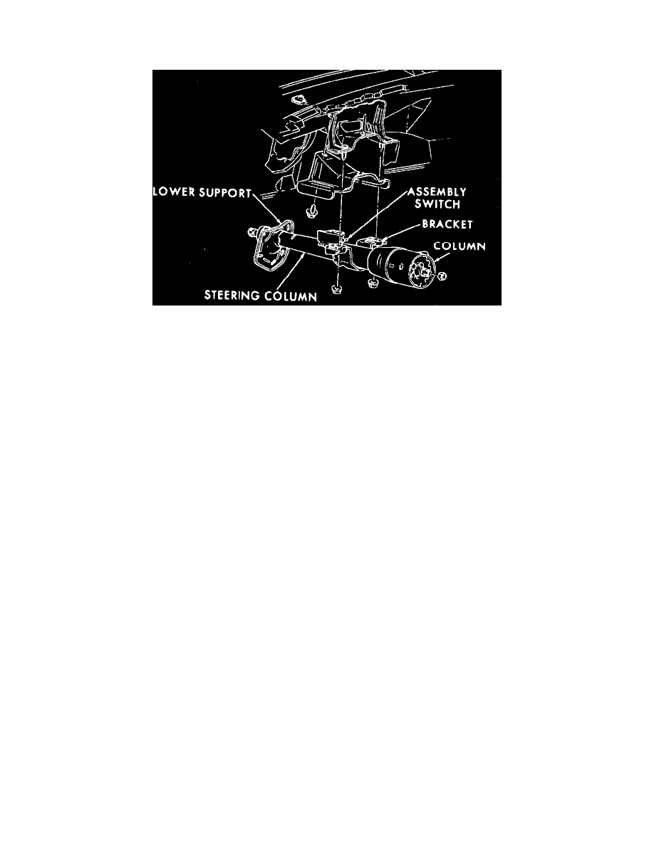
Fig. 4 Typical steering column installation. Cadillac Rear Wheel Drive Models & 1982---85 Eldorado & Seville
CADILLAC REAR WHEEL DRIVE MODELS & 1982---85 ELDORADO & SEVILLE
REMOVAL
1.
Center steering wheel to gain access to upper coupling pinch bolt and nut.
2.
Disconnect battery ground cable.
3.
Disconnect transmission linkage at lower shift lever, then remove pinch bolt and separate intermediate shaft from spline.
4.
On all models except Eldorado and Seville, remove four screws attaching steering lower cover to instrument panel, then remove cover.
5.
On Eldorado and Seville, loosen 4 screws attaching rear edge of lower instrument panel cover to instrument panel base assembly. Open ashtray,
then remove two screws through access holes located under ashtray housing assembly. Remove six screws from front edge of instrument panel
lower cover and remove cover. Note that the two longer mounting screws are located below the steering column.
6.
Disconnect turn signal wiring at connector. Also disconnect cruise control wiring at this time.
7.
Remove screw attaching shift indicator cable to shift bowl.
8.
Loosen two screws at steering column upper support, Fig. 4, and on Seville models, remove shims.
9.
Move toe pan seal up on steering column as far as possible, then position carpet out of way to gain access to toe pan.
10.
On all models except Eldorado and Seville, remove five screws attaching toe pan bracket to toe pan. On Eldorado and Seville, remove four screws
attaching toe pan bracket to toe pan.
11.
On Eldorado and Seville, remove lower support and bracket assembly.
12.
On all models, remove two nuts attaching upper column bracket to column support, then disconnect ignition and back-up light switch connectors
and parking brake release hose. On models equipped with automatic door locks, disconnect wire connector.
13.
Carefully pull steering column up and out of vehicle, using care not to damage column mounted switches or dash seal. If shaft binds on upper
coupling, reattach column upper mounting bracket and pry shaft from coupling using a screwdriver.
INSTALLATION
Exc. Eldorado & Seville
1.
Position toe pan seal on column, if removed.
2.
Insert lower end of steering column through hole in toe pan and into flex coupling, aligning coupling and steering shaft flats. Use care not to
damage lower shift lever or back-up light switch.
3.
Connect ignition switch wire connector, then install two nuts to secure upper column bracket to column support. Do not tighten nuts at this time.
4.
Connect back-up light and turn signal switch wire connector, parking brake release hose and automatic door lock and Cruise Control wiring
harness, if equipped.
5.
Install screw in toe plate locator hole, aligning toe plate to toe pan, then install four attaching screws and torque to 50 in. lbs.
6.
Install toe pan insulator at column support.
7.
Install carpet at lower column support, then position toe pan seal over carpet.
8.
Tighten upper column mounting bracket to upper column support nuts to 20 ft. lbs.
9.
Position shift pointer cable to shift bowl, then install attaching screw and check for proper alignment.
10.
Install steering column lower cover.
11.
Connect transmission linkage at lower shift lever.
12.
Secure upper coupling to steering shaft. Clearance between steering shaft and upper coupling should be 5/16 in., otherwise damage to lower
bearing may result. Torque pinch bolt to 45 ft. lbs.
13.
Connect battery ground cable.