
Fleetwood V8-368 6.0L VIN 9 FI (1982)
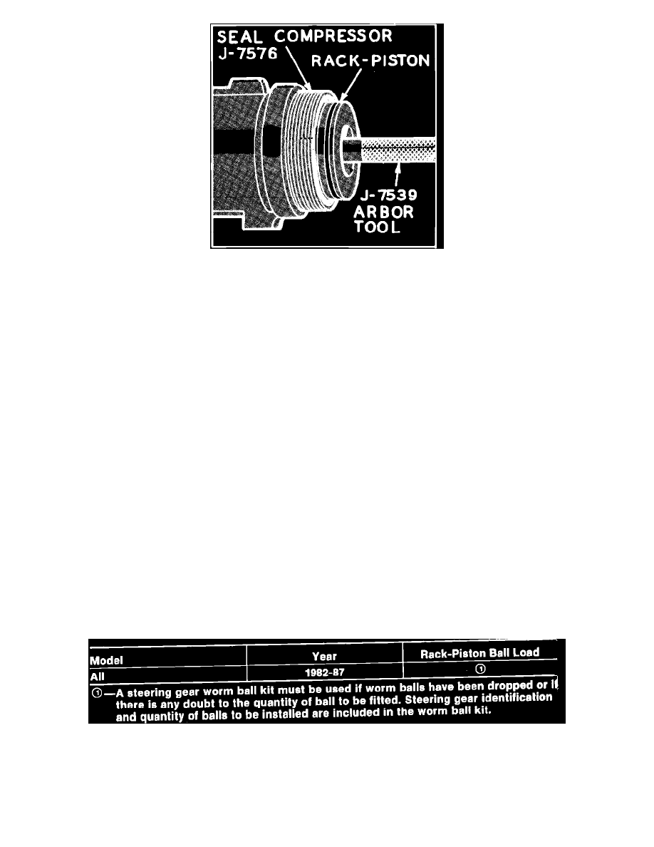
Fig. 28 Installing rack-piston seal compressor
1.
Position gear housing in vise with adjuster plug end facing up.
2.
Lubricate worm shaft, lower thrust bearing and races with power steering fluid, then position thrust bearing and race on worm.
3.
Align valve body drive pin on worm with narrow pin slot on valve body. Be sure O-ring seal between valve body and worm head is installed.
4.
Position valve body and worm shaft in housing as a unit.
Do not push against stub shaft as this might cause stub shaft and cap to pull out of
valve body, allowing spool seal to slip into valve body oil grooves. Valve assembly can be installed by pushing on outer diameter of valve
body housing with the fingers of both hands. Make certain that Teflon rings are not binding on inside of housing. Valve is properly seated
when oil return hole in gear housing is fully visible.
5.
Place a suitable seal protector over end of stub shaft,
Fig. 27.
6.
Lubricate new adjuster plug O-ring seal with power steering fluid and install in groove on adjuster plug.
7.
Install adjuster plug over end of stub shaft and tighten just enough to make certain that all parts are properly seated in gear housing. Remove seal
protector.
8.
Install adjuster plug locknut loosely on adjuster plug.
9.
Install seal compressor in gear housing, holding it tightly against shoulder in housing,
Fig. 28.
10.
Insert rack-piston into housing until arbor engages worm. Turn stub shaft clockwise, using an 11/16 in. wrench to draw rack-piston into housing.
When piston ring is in housing bore, arbor and seal compressor can be removed.
11.
Turn stub shaft as necessary until middle rack groove in rack-piston is aligned with center of pitman shaft needle bearing.
12.
Lubricate new side cover O-ring seal and install in groove in face of side cover.
13.
Assemble side cover on pitman shaft by screwing cover onto adjusting screw until cover bottoms on pitman shaft.
14.
Install pitman shaft so that center tooth in sector meshes with center groove of rack-piston. Make sure side cover O-ring is in place before pushing
side cover down on gear housing.
15.
Install side cover screws and lockwashers.
16.
Hold adjuster screw with Allen wrench and install new adjuster locknut halfway on adjuster screw.
17.
Install rack-piston end plug in rack-piston and tighten plug to 75-80 ft. lbs.
18.
Lubricate new housing end plug O-ring seal with power steering fluid and install in gear housing.
19.
Insert end plug into gear housing and seat against O-ring seal. Slight tapping with a mallet may be necessary to seat end plug properly.
20.
Snap end plug retainer ring into place with fingers. Slight tapping may be required to bottom ring in housing securely. Install coupling flange.
Assemble Rack-Piston & Worm
Fig. 20 Rack-Piston ball specification chart