
Fleetwood V8-368 6.0L VIN 9 FI (1982)
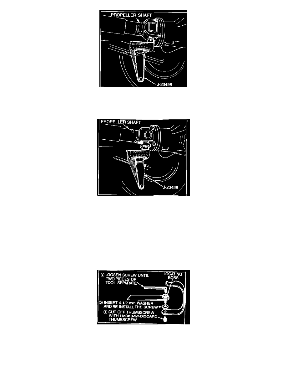
FIGURE 3 - CHECKING REAR UNIVERSAL JOINT ANGLE
A.
Place inclinometer on rear propeller shaft bearing cap. Center bubble in sight glass and record measurement. Bearing cap must be
straight up and down and free of dirt or other foreign material to obtain an accurate measurement, refer to Figure 3.
FIGURE 4 - CHECKING REAR UNIVERSAL JOINT ANGLE
B.
Rotate propeller shaft 90~ and place inclinometer on rear drive yoke bearing cap. Center bubble in sight glass and record measurement,
refer to Figure 4.
C.
Subtract smaller figure from larger figure to obtain the rear universal joint angle. Joint angle should be 2~.
D.
If joint angle is not 2~, loosen all eight rear control arm bolts and jack the pinion nose up or pull down as needed to obtain a 2~ joint
angle.
E.
With the pinion nose at desired location and with the rear axle assembly raised to its fully-loaded position, torque the control arm bolts.
Using this procedure bring the angle as close to the specification as possible, approximately a 1~ angle change may be obtained.
FIGURE 5 - REVISING INCLINOMETER ADAPTER
VII. Check propeller shaft front universal joint angle.
A.
Due to revisions in production tolerances, the inclinometer adapter (J2349820) may not fit onto some front cardan joints because of