
Fleetwood V8-368 6.0L VIN 9 FI (1982)
interference with the transmission cross-member. To revise the adaptor to make it fit on cars with a single cardan prop-shaft, follow the
procedure below:
1.
Cut off the thumb screw with a hacksaw, refer to Figure 5. Discard thumbscrew.
2.
Using an Allen wrench, refer to Figure 5, loosen the screw from the inside of the tool until the two pieces of the tool separate.
3.
Insert a washer approximately 4-1/2 mm (3/16") thick between the two pieces of the tool and hold in place by reinstalling the screw,
refer to Figure 5.
4.
Grind off the end of the screw until it is flush with the tool.
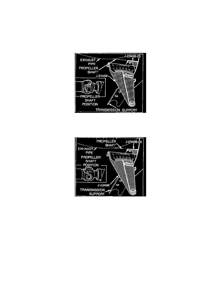
FIGURE 6 - CHECKING FRONT UNIVERSAL JOINT ANGLE
B.
Place inclinometer adapter on front propeller shaft bearing cap. Place the inclinometer on the adaptor then center the bubble in sight glass and
record measurement, refer to Figure 6.
FIGURE 7 - CHECKING FRONT UNIVERSAL JOINT ANGLE
C.
Rotate propeller shaft 90~ and place inclinometer adaptor in front slip spline yoke bearing cap. Place the inclinometer on the adaptor then
center the bubble on sight glass and record measurement, refer to Figure 7.
D.
Subtract smaller figure from larger figure to obtain the front universal joint angle. The front joint angle should be 2~.
E.
If joint angle is not 2~, add or remove shims between the transmission and the transmission mount to obtain a 2~ joint angle.
F.
Repeat step VI if correction was made in step VII.
VIII. With both rear tire and wheel assemblies removed, reinstall wheel lug nuts with flat side next to drum then check propeller shaft balance as follows:
A.
Mark and number propeller shaft at four points 90~ apart at rear of shaft just forward of balance weight.
B.
Install two hose clamps on the swedged down portion of !he propeller shaft. Align both clamps to any one of the four marks made on the shaft
in step A. Tighten the clamps. Be sure sufficient clearance is maintained so that clamp heads do not contact floor pan of car.
C.
Run the car through the suspect speed range. Note amount of unbalance.
D.
Loosen clamps and rotate clamp heads 90~ to next mark on shaft. Tighten clamps and repeat step C.