
RAM 1500 Truck 4WD V8-5.9L VIN Z (2002)
The voltage network used to transmit messages requires biasing and termination. Each module on the PCI data bus system provides its own biasing
and termination in order to transmit and receive messages. Each module (also referred to as a node) terminates the bus through a terminating
resistor and a terminating capacitor. There are two types of nodes on the bus. The dominant node terminates the bus through a 1 KW resistor and a
3300 pF capacitor. The Powertrain Control Module (PCM) is the only dominant node for the PCI data bus system. A standard node terminates the
bus through an 11 KW resistor and a 330 pF capacitor.
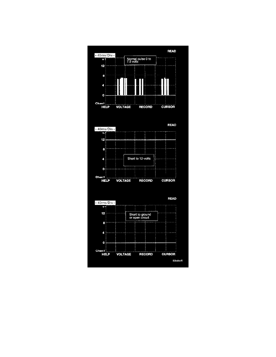
The modules bias the bus when transmitting a message. The PCI bus uses low and high voltage levels to generate signals. Low voltage is around 0
volts when no modules are transmitting and the high voltage is about 7-1/2 volts when modules are transmitting. Since there is only voltage
present when the modules transmit and the message length is only about 500 milliseconds, it is ineffective to try and measure the bus activity with
a conventional voltmeter. The preferred method is to use the DRB III lab scope. The 12v square wave selection on the 20-volt scale provides a
good view of the bus activity. Voltage on the bus should pulse between 0 and about 7-1/2 volts. Refer to the figure for some typical displays.
The low and high voltage levels are generated by means of variable-pulse width modulation to form signals of varying length. The Variable Pulse
Width Modulation (VPWM) used in PCI bus messaging is a method in which both the state of the bus and the width of the pulse are used to
encode bit information. A "zero" bit is defined as a short low pulse or a long high pulse. A "one" bit is defined as a long low pulse or a short high
pulse. A low (passive) state on the bus does not necessarily mean a zero bit. It also depends upon pulse width. If the width is short, it stands for a
zero bit. If the width is long, it stands for a one bit. Similarly, a high (active) state does not necessarily mean a one bit. This too depends upon
pulse width. If the width is short, it stands for a one bit. If the width is long, it stands for a zero bit.
In the case where there are successive zero or one data bits, both the state of the bus and the width of the pulse are changed alternately. This