
Testing the field coils
- Make
- Fiat
- Model
- 500 Classic Workshop Manual
- Year
- 1957–1975
- Section
- The starter › Testing the field coils
Testing the field coils
Use a 12 volt bulb in one lead of a 12 volt battery. Connect one lead to the brush connection joint to the coil field and the other to the field coil current supply lead. If the bulb does not light there is a break in the field coil windings. This is not a complete test as it is still possible for a coil to be earthed. Check this by moving the lead from the brush connection and holding it on a clean metal surface on the yoke or body. If the bulb lights it shows that the field coils are earthed.
The only sure way of curing faulty field coils is to take the starter motor to a service station.
Examining the armature
The armature shaft may be bent due to the starter being operated whilst the engine is operating. Do not try to straighten a bent shaft or machine the armature core to obtain the correct clearance.
If the commutator is damaged or any wires or segments have lifted from it, the assembly will have to be renewed.
Starter bearings
Bearing bushes are of the porous bronzed type and must not be reamed after fitting. Worn bearings should be withdrawn by screwing a tap into them and pulling on the tap. New bushes must be immersed in engine oil for approximately twenty four hours before fitting. Press them into place using a suitably sized drift which has a spigot the length of the bearing and the diameter of the starter shaft. When this is withdrawn after fitting, the bore of the bush should be correct to size.
The pinion drive
This unit is shown in FIG 11:5. The chief sources of trouble are a dirty unit or a broken starting engagement regulator adjustment arm 6 Cutout adjustment blade spring 7 Soldering of cutout shunt and series winding
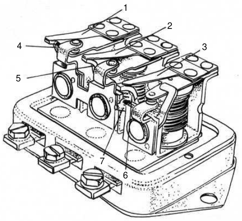
| 1 | Voltage regulator adjusting spring |
| 2 | Current regulator adjusting spring |
| 3 | Cutout adjusting spring |
| 4 | Voltage regulator adjustment arm |
| 5 | Current |
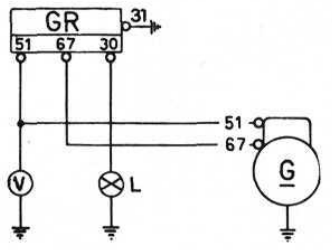
| GR Regulator GN 1.12.16 G Generator | |
| V | Voltmeter, 20 V scale (0.5% accuracy) L 12 V, 3 to 5 W bulb |
FIAT DSV 90.12.1 6.3 S
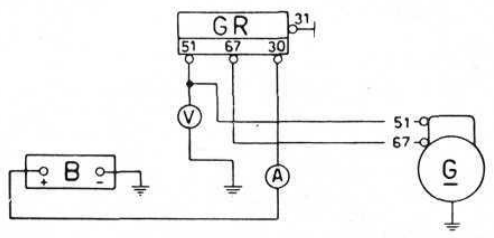
| GR Regulator GN 1.1 2.1 6 G Generator FIAT DSV 90.1 2.1 6.3 S | |
| B | Battery, 50 Ah, fully charged |
| A | Ammeter, asymmetrical scale 10-0-15 A |
| V | Voltmeter |
| 20 | V scale (0.5% accuracy) |
spring 13. Should any defect be found then the pinion assembly must be renewed as one complete unit. After examining to ensure that there are no defects thoroughly clean using petrol.
Reassembling and refitting the starter
In both cases this is a simple reversal of the dismantling procedure. Grease the drive splines and the engagement lever groove in the sleeve.
Parts & tools for this job For 1957 Fiat 500 Classic
- TOOLBattery testerSearch: car battery tester
- TOOLDigital multimeterSearch: automotive digital multimeter
- TOOLBattery terminal cleanerSearch: battery terminal cleaner
Links open Amazon search results in a new tab. As an Amazon Associate I earn from qualifying purchases.