
Wheel geometry
- Make
- Fiat
- Model
- Bravo /Brava (182) Factory Service Manual
- Year
- 1995–2001
- Section
- Wheels (98 range) › Wheel geometry
00 Introduction and technical dataWheel geometry
WHEEL GEOMETRY
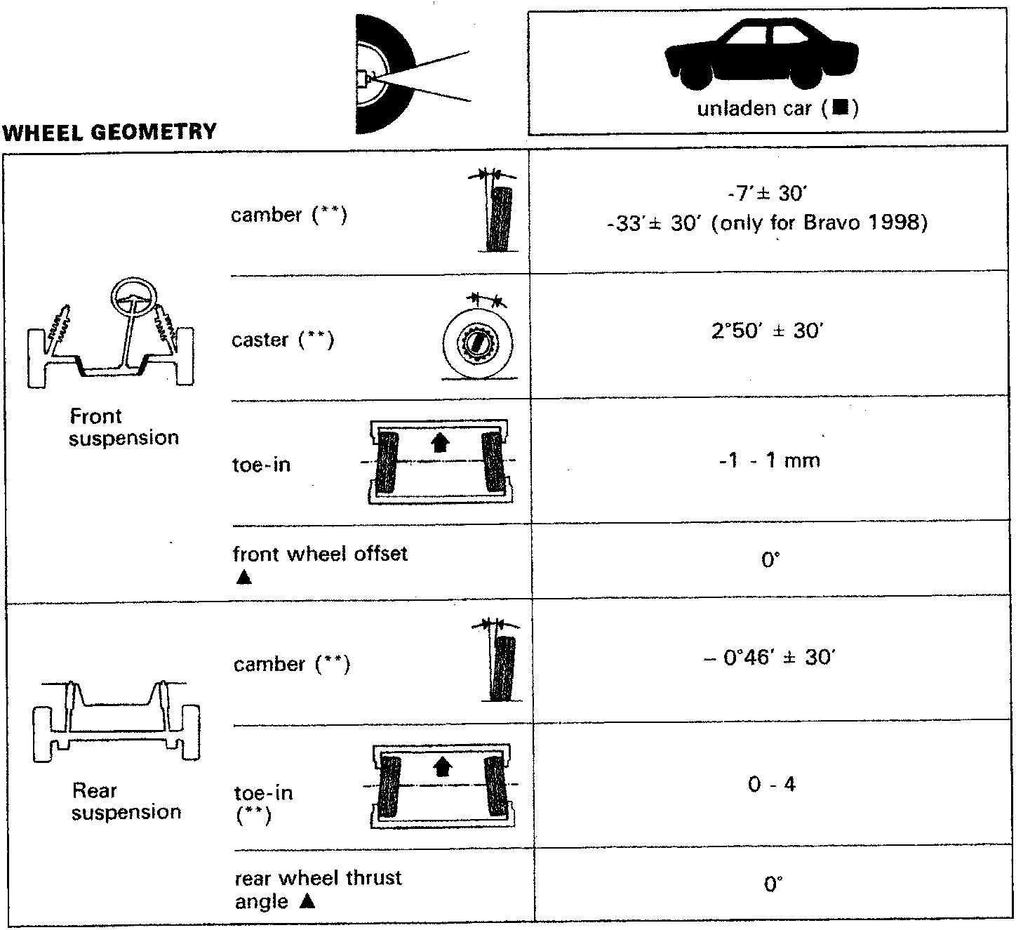
| Front suspension |
camber (**) | -7' ± 30' -33' ± 30' (only for Bravo 1998) |
| caster (**) | 2°50' ± 30' | |
| toe-in | -1 - 1 mm | |
| front wheel offset ▲ | 0° | |
| Rear suspension |
camber (**) | - 0°46' ± 30' |
| toe-in (**) |
0 - 4 | |
| rear wheel thrust angle ▲ |
0° |
(**) Angles cannot be adjusted
(■) With tyres inflated to the correct pressure and vehicle in running order with 5 litres of fuel
(▲) Non-adjustable angles, used for correct vehicle alignment
Parts & tools for this job For 1995 Fiat Bravo
Links open Amazon search results in a new tab. As an Amazon Associate I earn from qualifying purchases.