
Removing - refitting
- Make
- Fiat
- Model
- Bravo /Brava (182) Factory Service Manual
- Year
- 1995–2001
- Section
- Removing-refitting (1747 16v) › Removing - refitting
21 Gearbox and differentialRemoving - refitting
Removing - refitting
21-27.
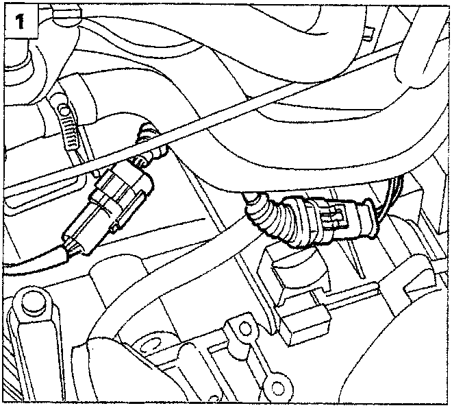
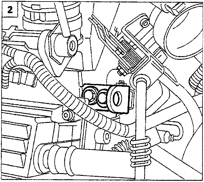
1.
Disconnect the electrical connector of the odometer signal and the Lambda probe connector.
2.
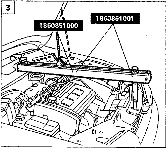
Using two ordinary bolts, install a suitable supporting eyelet for hooking the power unit support stand.
3.
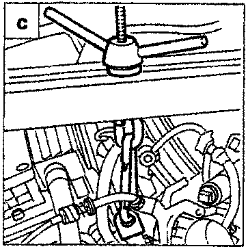
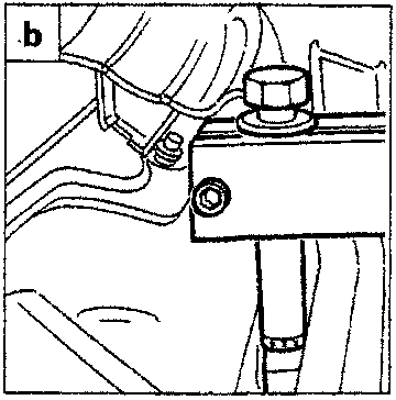
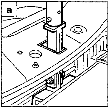
Fit the engine support stand 1860851000 and adaptor 1860851001 in the appropriate mountings.
- Front mounting: place the tool in the seat of the safety catch so that it rests on the front crossframe.
- Rear mounting: fit the tool level with the central reinforcement of the fire-proof bulkhead.
- secure the hook of the crossbeam to the previously secured bracket.
Parts & tools for this job For 1995 Fiat Bravo
- TOOLTorque wrenchSearch: 3/8 inch torque wrench
- TOOLSocket setSearch: socket set metric
- BOOKHaynes manualSearch: Haynes manual Fiat Bravo
Links open Amazon search results in a new tab. As an Amazon Associate I earn from qualifying purchases.