
MG 295 (page 4 of 4)
- Make
- Fiat
- Model
- Bravo /Brava (182) Factory Service Manual
- Year
- 1995–2001
- Section
- Connector blocks (2000 range)
55 Electrical systemMG 295 · page 4 of 4
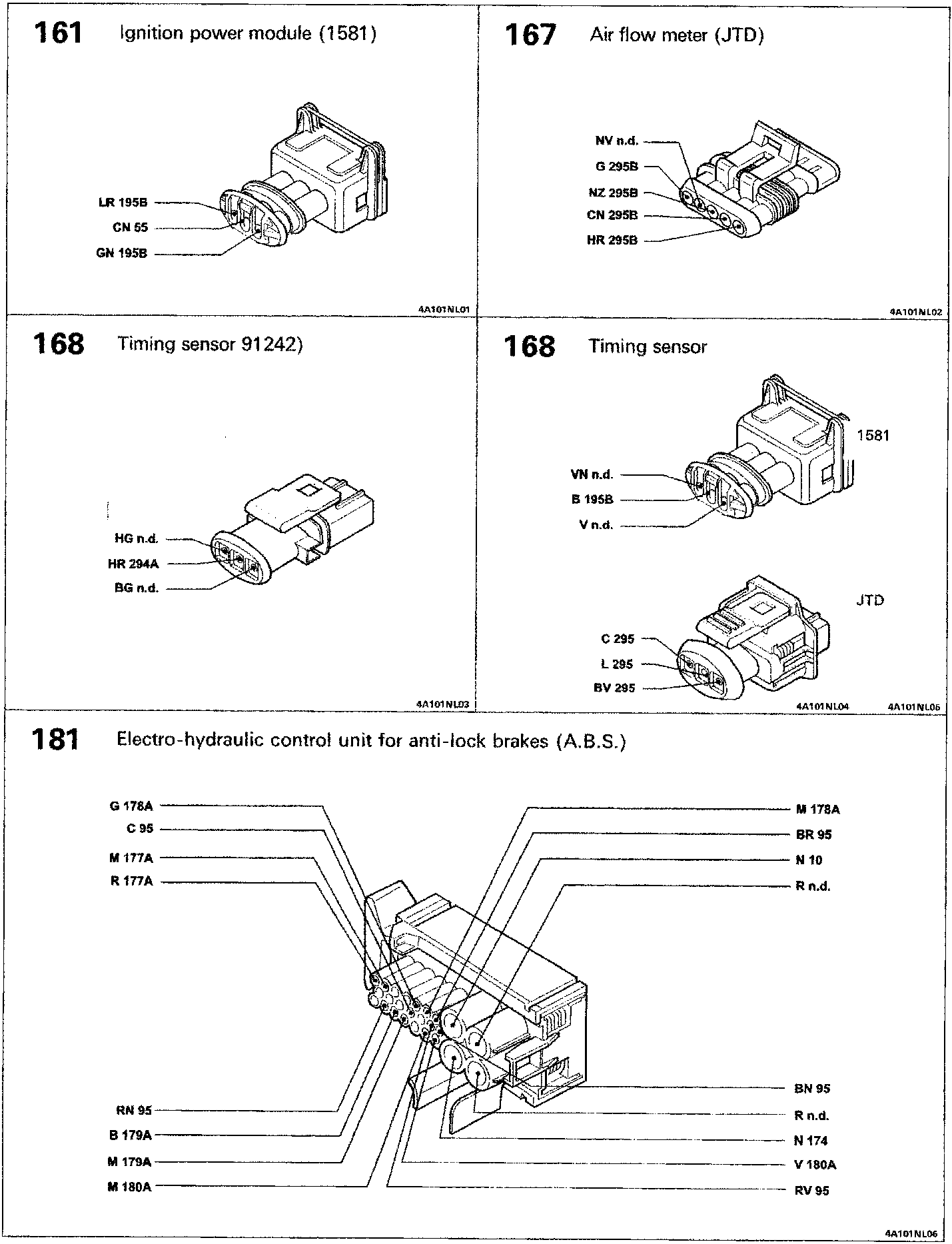
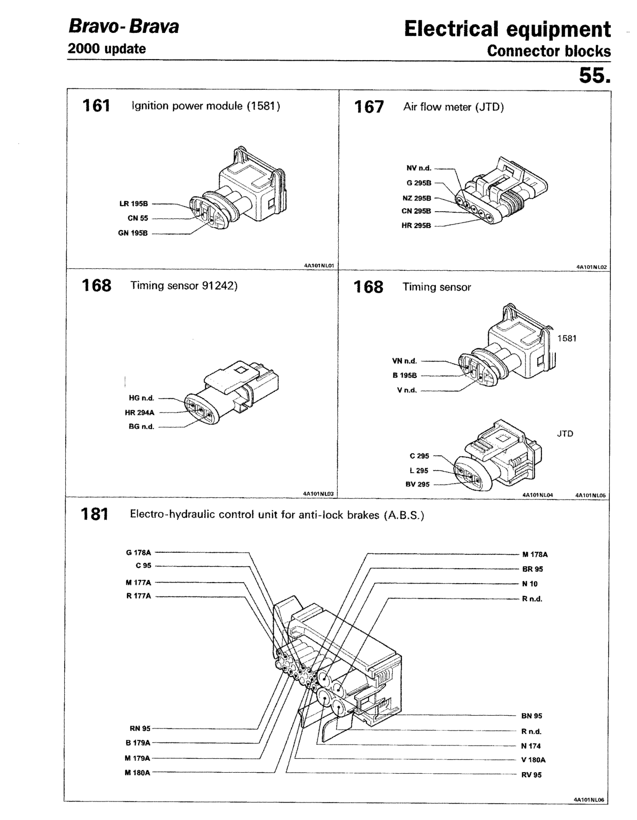
- Ignition power module (1581)
- LR 195B
- CN 55
- GN 195B
- Air flow meter (JTD)
- NV n.d.
- G 295B
- NZ 295B
- CN 295B
- HR 295B
- Timing sensor 91242)
- HG n.d.
- HR 294A
- BG n.d.
- Timing sensor
(1581)
- VN n.d.
- B 195B
- V n.d.
(JTD)
- C 295
- L 295
- BV 295
- Electro-hydraulic control unit for anti-lock brakes (A.B.S.)
- G 178A
- C 95
- M 177A
- R 177A
- RN 95
- B 179A
- M 179A
- M 180A
- M 178A
- BR 95
- N 10
- R n.d.
- BN 95
- R n.d.
- N 174
- V 180A
- RV 95
Original page
Parts & tools for this job For 1995 Fiat Bravo
- TOOLDigital multimeterSearch: automotive digital multimeter
- PARTAssorted fuse kitSearch: car fuse assortment kit
- TOOLWire crimper and connector kitSearch: wire crimper connector kit
Links open Amazon search results in a new tab. As an Amazon Associate I earn from qualifying purchases.