
Fault diagnosis
- Make
- Fiat
- Model
- Bravo /Brava (182) Factory Service Manual
- Year
- 1995–2001
- Section
- Fault diagnosis (99 range) › Fault diagnosis
55 Electrical systemFault diagnosis · page 1 of 2
Fault diagnosis
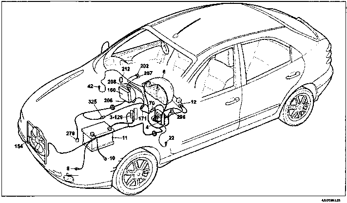
Version without automatic air conditioning
Engine cooling - Engine coolant temperature gauge - Car interior ventilation
Key to components
- 3 Power fuse box:
- 30A fuse protecting injection system
- 40A fuse protecting ignition system
- 80A fuse protecting additional extras
- 80A fuse protecting junction unit
- 4 Junction unit
- E1 Switch discharge relay
- 6 Instrument panel.
- X Engine coolant temperature gauge
- Y Electronic module
- 8 Left front earth
- 10 Earth for battery on bodysell
- 11 Battery
- 12 Ignition switch
- 22 Left dashboard earth
- 42 Right dashboard earth
- 70 Connection between dashborad/front cables
- 129 40A power fuse protecting engine cooling fan
- 154 Engine cooling fan
- 160 Injection/ignition electronic control unit (11747)
- 171 Connection for heater unit cables
- 202 Bulbs for heater unit/air conditioning
- 206 Heater/air conditioning fan
- 207 Heater/air conditioning system speed control switch
- 208 Heater/air conditioning system limit resistor Engine cooling fan relay feed
- 212 Engine cooling fan relay feed
- 279 Engine coolant temperature twin sender unit
- 296 Fuse holder base on front cable
- C 7.5A fuse protecting electronic injection/cooling system Fiat-CODE
- 325 Connection between injection/left front cables
N.D. Ultrasound welding taped into wiring
6A Instrument panel
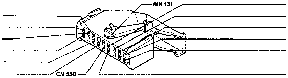
70 Connection between dashboard/front cables
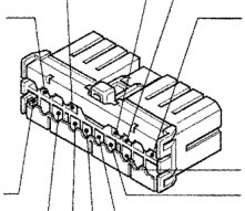
* Variant connection for ELX trim level
** Variant connection for versions with alarm
171 Connection for heater unit cables
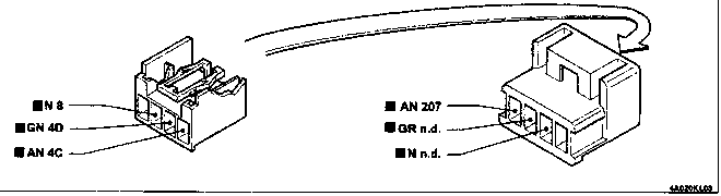
Leads involved in the wiring diagram are marked by a square
Parts & tools for this job For 1995 Fiat Bravo
- TOOLDigital multimeterSearch: automotive digital multimeter
- PARTAssorted fuse kitSearch: car fuse assortment kit
- TOOLWire crimper and connector kitSearch: wire crimper connector kit
Links open Amazon search results in a new tab. As an Amazon Associate I earn from qualifying purchases.