
Key to components
- Make
- Fiat
- Model
- Bravo /Brava (182) Factory Service Manual
- Year
- 1995–2001
- Section
- Fault diagnosis (99 range) › Key to components
55 Electrical systemKey to components
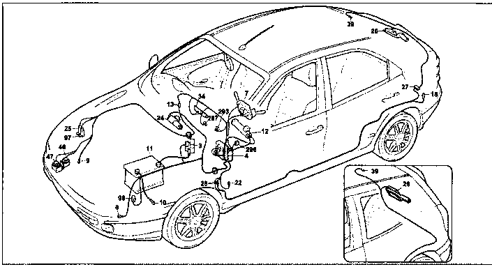
Version without A.B.I.
Windscreen wash/wipe - Rearscreen wash/wipe - Electric horns - Heated rear windscreen and warning light - Headlamp washer
Key to components
- Power fuse box:
- A 30A fuse protecting injection system
- B 40A fuse protecting ignition system
- C 80A fuse protecting additional extras
- D 80A fuse protecting junction unit
- Junction unit
- E1 Switch discharge relay
- E2 Electric horn relay feed
- E3 Heated rear windscreen relay feed
- Steering column switch unit:
- A Windscreen wiper speed control switch
- B Windscreen washer/headlamp washer/rearscreen washer control switch
- C Rearscreen wiper control switch
- D Headlamp flasher button
- E Dipped/main beam headlamps control switch
- F Side lights control switch
- G Direction indicators/hazard warning lights intermittent device
- H Direction indicators control switch
- I Electric horn control button
- Left front earth
- Right front earth
- Earth for battery on bodyshell
- Battery
- Ignition switch
- Connection between right/left front cables
- Left rear earth
- Left dashboard earth
- Windscreen wiper motor
- Electric windscreen/rearscreen washer pump
- Rearscreen wiper motor
- Contact board between bodyshell and tail-gate (Brava)
- Connection between dashboard/longitudinal cables
- Switch control panel:
- A Alarm on warning light
- B Rear fog lamps control switch
- D Rear fog lamps warning light
- E Heated rear winscreen control switch
- F Heated rear windscreen warning light
- G Switch control panel ideogram light
- H Fog lights warning light
- I Fog lights control switch
- L Outside temperature control switch
- Heated rear windscreen
- Left horn
- Right horn
- Electric headlamp washer pump
- Headlamp washer intermittent device
- Short circuit connection
- Fuse holder base on dashboard cable
- A 7.5A fuse protecting switch panel light; Radio telephone, Radio; Electric mirrors
- B Fuse holder base on front cable
- B 20A fuse protecting windscreen wiper with A.B.I. or without A.B.I.
N.D. Ultrasound welding taped in cable loom
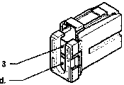
4A Junction unit
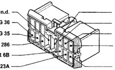
4I Junction unit
28 Connection between dashboard/longitudinal cables Versions without A.B.I. control unit
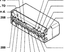
- Variant connection for versions with alarm
- Variant connection for versions with top of the range radio
- ** Variant connection for Brava versions
- *** Variant connection for Brava versions with alarm
Leads involved in the wiring diagram are marked by a square
Parts & tools for this job For 1995 Fiat Bravo
- TOOLDigital multimeterSearch: automotive digital multimeter
- PARTAssorted fuse kitSearch: car fuse assortment kit
- TOOLWire crimper and connector kitSearch: wire crimper connector kit
Links open Amazon search results in a new tab. As an Amazon Associate I earn from qualifying purchases.