
Service control unit
- Make
- Fiat
- Model
- Bravo /Brava (182) Factory Service Manual
- Year
- 1995–2001
- Section
- Services control unit (98 range) › Service control unit
55 Electrical systemService control unit
Service control unit
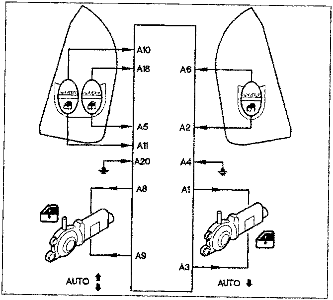
FRONT ELECTRIC WINDOW OPERATION
Safety systems
The window stops (i.e. motor electrical supply is cut off) when the glass reaches the upper or lower end stop or if an obstacle gets in the way and blocks the glass. This is regulated by controlling the self-adaptive motor direct current. The electronic control unit behaves as follows:- If the motor control signal cuts out during operation, the control unit deactivates the system within a maximum time of 500 milliseconds. This interruption occurs when the controlled current taken up by the electric window motor drops to less than 0.8 A.
- If the control buttons are faulty (short-circuit or keys stuck down), control operation is inhibited at the time of control unit activation until the defect disappears (or the key is released) for longer than 60 milliseconds;
- if the buttons are pressed for longer than 12 seconds, motor operation is inhibited; if the descending key is short-circuited or pressed for longer than 30 seconds, the control is inhibited so that the glass can be closed.
DOOR LOCK/RELEASE
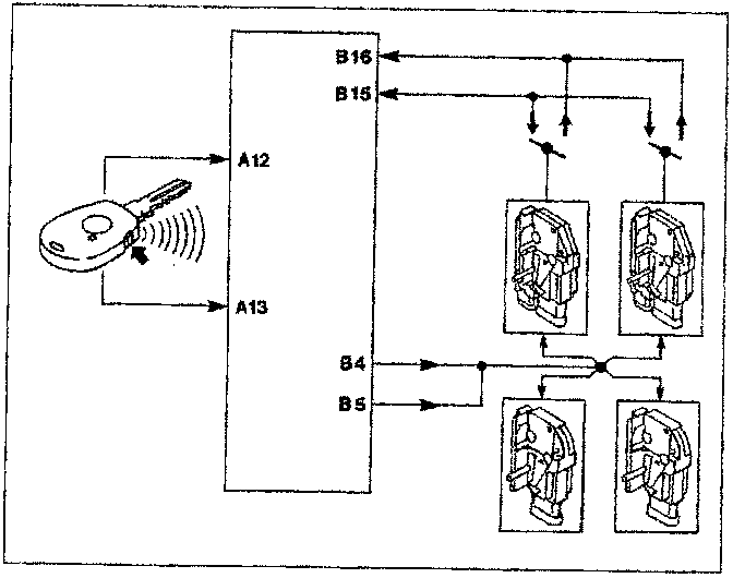
NOTE Locking takes place only with the doors properly closed and the locks locked. Conversely, release takes place with the doors properly closed and the doors locked.
Parts & tools for this job For 1995 Fiat Bravo
- TOOLDigital multimeterSearch: automotive digital multimeter
- PARTAssorted fuse kitSearch: car fuse assortment kit
- TOOLWire crimper and connector kitSearch: wire crimper connector kit
Links open Amazon search results in a new tab. As an Amazon Associate I earn from qualifying purchases.