
Introduction - CURRENT GENERATOR
- Make
- Fiat
- Model
- Doblò Factory Service Manual
- Year
- 2000–2010
- Section
- Current generation › Introduction - CURRENT GENERATOR
Introduction - CURRENT GENERATOR
LOCATION OF COMPONENTS ON VEHICLE
The following figure shows component location.
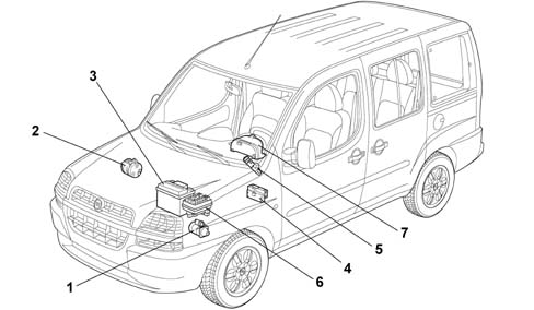
1 Starter motor (A20)
2 Alternator (A10)
3 Battery (A1)
4 Electronic management control unit (M1) (Body Computer)
5. Ignition lock barrel (H1)
6. Junction unit (B 1)
7. Instrument panel (E 50)
FUNCTIONS
The vehicle is equipped with a starting and recharging system which has the following functions:
- The starting circuit has the function of turning the engine over, at a certain speed, to allow the engine management control unit to trigger the ignition.
- The recharging circuit has the function of guaranteeing all the energy required for correct operation for the system and the individual electrical/electronic on-board devices.
FUNCTIONS
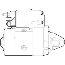
Types of starter motors fitted on the vehicle according to the version:
| Engine | Supplier | Model | Rated power | Rated voltage |
|---|---|---|---|---|
| 1242 8V | Magneti Marelli | EMM 12.51 | 0.9 kW | 12V |
| 1910 D | Bosch | EMB 38.01 | 2.0 kW | 12V |
| 1910 D | Denso | EMM 36.01 | 1.8 kW | 12V |
FUNCTIONS
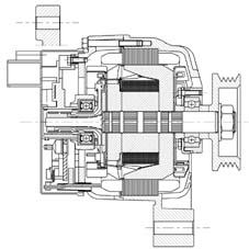
The alternator is a rotary machine which transforms mechanical energy into electrical energy.
FUNCTIONS
If recharging signals are not present or irregular, carry out the following checks before dismantling the alternator:
- Check belt tension
- Check the nut on the positive alternator terminal (B+) is tight and ensure the washer is present
- Check the nut on the excitation terminal (D+) is tight and ensure the washer is present
- Check that the nuts on the positive junction unit in the engine bay are tight
- Check the bolts securing the negative terminal to the body are tight
- Check the battery terminals are clean and fully tight
Types of alternators fitted on the vehicle according to the version:
| Engine | Description | Supplier |
|---|---|---|
| 12428V without air conditioner | A 115l - 14V- 33 /60 A | Denso |
| 12428V with air conditioner | A 115l - 14V- 40 /75 A | Magneti Marelli |
| 1910 D | A 115l - 14V- 40 /75 A | Denso |
| 1910 D | A 115l - 14V- 50 /90 A | Denso |
OPERATING PRINCIPLE
The alternator shaft (rotor) is turned by the crankshaft by means of a belt.
The rotor produces a magnetic field that induces an alternating current in the fixed coil (stator).
A diode rectifier bridge, at the back of the alternator, transforms the alternating current into a direct current which is sent to recharge the battery and supply the various devices.
A voltage regulator, also built into the alternator, maintains a constant voltage supply at around 14 Volt for all engine load and speed ranges.
Two small internal radial fans cool the alternator. When the ignition key is turned to the ON position, a supply signal controlled by the ignition reaches alternator terminal D+, via the Body Computer.
If the Body Computer does not provide the energizing signal, the alternator is energized at 1000 engine rpm (about 2200 alternator rpm) to make use of the residual magnetic field.
The ''RTM Puls'' voltage regulator on receiving this signal, in turn, energizes the rotor coil to create a minimal electro-magnetic field to generate the magnetic poles (alternating north and south). When the engine is started up, a rotary motion is transmitted to the alternator, thereby also causing the rotation of the electro-magnetic field which, cutting the coils of the three stator windings, produces an alternating induced voltage.
The resulting voltage cannot be used directly by the vehicle system. Before distribution, it is rectified by means of an electrical circuit with a bridge configuration made up of 6 Zener diodes.
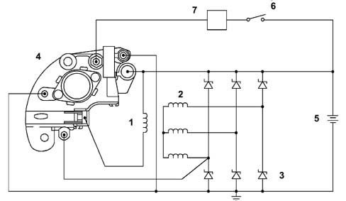
1 Alternator rotor
2 Alternator stator
3 Pressfit Zener diode bridge
4 TIP voltage regulator
5. Battery
6. Ignition key
7. Body computer (M1)
BATTERY
The following diagram shows correct battery electrolyte levels
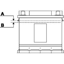
A. Maximum electrolyte level
B. Minimum electrolyte level
ELECTRICAL/MECHANICAL SPECIFICATIONS
Three different battery models are fitted to the Doblò
ELECTRICAL SPECIFICATIONS
| Battery | Power uptake Max. | Voltage | Internal elements |
|---|---|---|---|
| 48 Ah | 350A | 12V | Number of plates: 6 positive - 6 negative |
| 40 Ah | 200A | 12V | Number of plates: 4 positive - 3 negative |
| 50 Ah | 250A | 12V | Number of plates: 5 positive - 4 negative |
If it is discovered that the electrolyte level in one or more of the battery cells is below the minimum level on the plastic container, open the cover and add distilled or deoinized water (the same as for regular batteries).
Never subject the battery to rapid recharging at voltages above 15.5 Volt or to high recharging amperages.
Correct battery dimensions for model / trim level have been calculated to take into account power uptake when the ignition is switched off.
This absorption should not exceed 0.6 mA for each Ah of battery capacity; This is to ensure that, if the vehicle has been left for one month with all the consumers not controlled by the ignition switched on, residual battery capacity is half of nominal capacity, i.e. enough charge is left to start up the engine under normal environmental temperature conditions.
Parts & tools for this job For 2000 Fiat Doblò
- TOOLBattery testerSearch: car battery tester
- TOOLDigital multimeterSearch: automotive digital multimeter
- TOOLBattery terminal cleanerSearch: battery terminal cleaner
Links open Amazon search results in a new tab. As an Amazon Associate I earn from qualifying purchases.