
Wiring connector
- Make
- Fiat
- Model
- Punto (176) Factory Service Manual
- Year
- 1993–1999
- Section
- Fuel system (1242 16v) › Wiring connector
10 EngineWiring connector
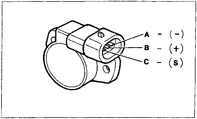
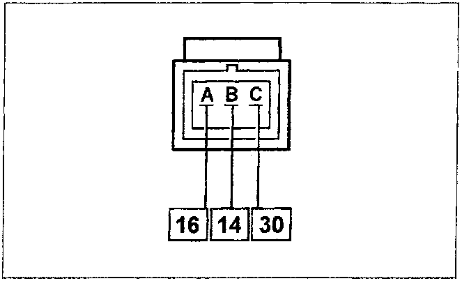
Wiring connector
The numbers indicate the corresponding control unit pins.Checking the electrical resistance
The sensor resistance can be measured in the following way: - connect an ohmmeter between pins A and B of the sensor and carry out the checked with a fixed resistance of 1440 ohm; - then connect the ohmmeter between pins A and C and on opening/closing the butterfly valve, check that the resistance value varies between 960 and 1440 ohm.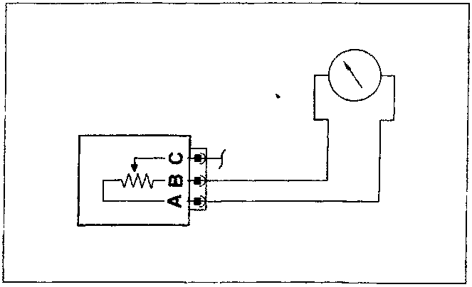
Recovery
An angular value is taken according to the engine speed and pressure relating to the nominal idle speed.Parts & tools for this job For 1993 Fiat Punto
- TOOLDigital multimeterSearch: automotive digital multimeter
- PARTAssorted fuse kitSearch: car fuse assortment kit
- TOOLWire crimper and connector kitSearch: wire crimper connector kit
Links open Amazon search results in a new tab. As an Amazon Associate I earn from qualifying purchases.