
Power unit
- Make
- Fiat
- Model
- Punto (176) Factory Service Manual
- Year
- 1993–1999
- Section
- Seats (Cabrio) › Power unit
Power unit
The power unit incorporates the deceleration sensor and the pre-loaded sprign which supplies the re-traction force for the webbing.
Inside the outer casing (1) there is a power spring (9) and a moving element (10), connected directly to the bowden cable (6) which has the task of transmitting the movement of the spring to the webbing locking unit.
With the device ready for operation, the spring (9) is loaded between the end (12) of the moving ele-ment (10) and the reaction element (7) washer (8) fixed to the structure of the seat. In the rear of the power unit there is a deceleration sensor (mass) (5), a reaction element for the spring fixing it to the seat (7) and the device (2) release levers. The mass is kept in the non intervention position by the pin (3) and the reaction spring (4). The safety clip (11) avoids the activation of the device because it prevent the mass from moving forwards (in the direction of the mass) and releasing the levers (2) which keep the moving element loaded by the spring (9).
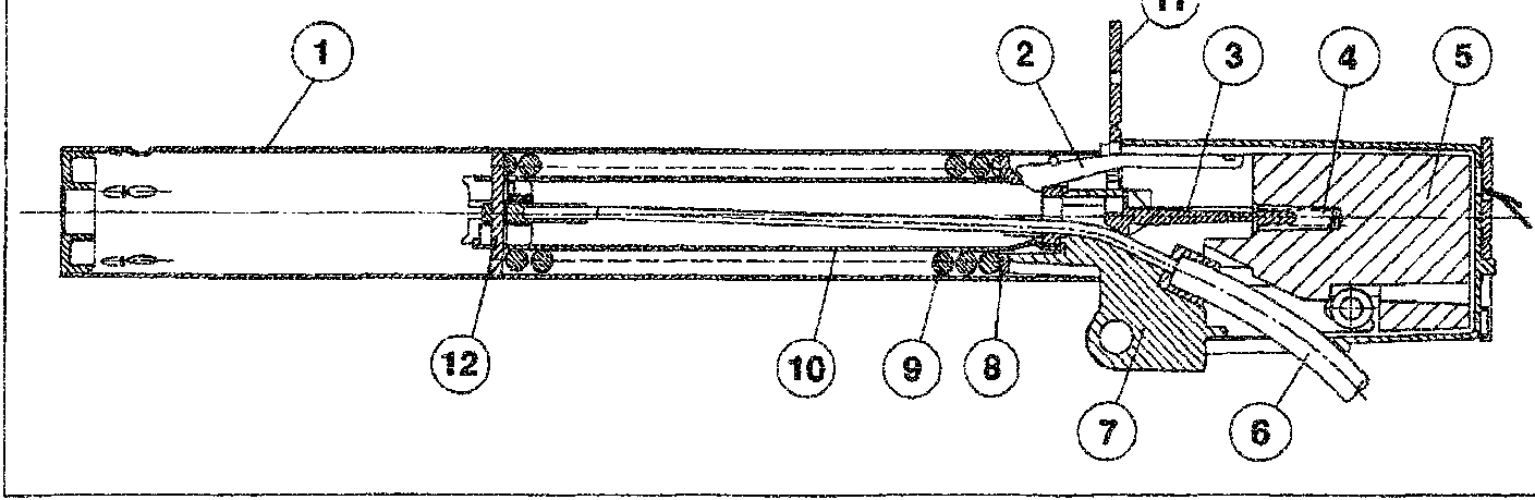
- Outer casing
- Locking lever
- Pin
- Reaction spring
- Deceleration sensor (mass)
- Bowden cable
- Element for fixing to seat
- Washer
- Pre-loaded spring
- Moving element
- Safety clip
- End of moving element
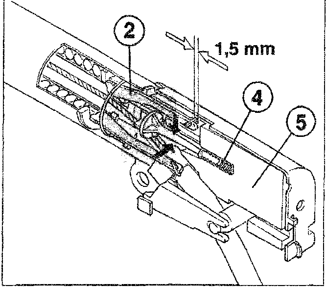
At the moment of impact, the inertia mass (5) moves forwards overcoming the reaction force of the spring (4). Through a movement of about 1.5 mm, the step on the front part of the mass releases the locking levers (2) al-lowing the operation of the device.
Parts & tools for this job For 1993 Fiat Punto
- TOOLTorque wrenchSearch: 3/8 inch torque wrench
- TOOLSocket setSearch: socket set metric
- BOOKHaynes manualSearch: Haynes manual Fiat Punto
Links open Amazon search results in a new tab. As an Amazon Associate I earn from qualifying purchases.