
Automatic transmission al4
- Make
- Fiat
- Model
- Ulysse Factory Service Manual
- Year
- 2002–2010
- Section
- Automatic transmission with differential › Automatic transmission al4
AUTOMATIC TRANSMISSION AL4
INTRODUCTION
The vehicle is fitted with an AL4 automatic transmission and differential with four speeds and reverse specially designed for front-wheel drive, transverse-engined vehicles. It belongs to the category of epicyclic gearboxes with a hydraulic torque converter electronically controlled by a microprocessor control unit.
The self-adaptive automatic transmission features two operating programs.
1st Program: self-adaptive with electronic control
The transmission adapts permanently to the driver's driving style and service conditions, depending on road profile and vehicle load.
The control unit chooses the most suitable speed transfer law from a range of 9:
- 3 driving style laws: these three laws refer to the driver's driving style (economic law, medium law, dynamic law) and are activated according to the driver's action on the accelerator pedal.
- 3 laws relating to road profile: these three laws refer to road profile (slight hill, steep hill, descent). When these are active, they preferentially select lower ratios and take priority over the driving style laws, with the exception of the dynamic law that takes priority over the slight hill and descent.
- 3 theoretical condition transfer laws: low temperature law: this activated during cold starts to ensure the gear casing is in the best possible conditions (oil temperature increase). High temperature law: this is activated when the engine/gear casing temperature becomes high yet not high enough to require the driver to be alerted. Anti-emission law: this is activated due to an increase in catalytic converter temperature.
The self-adaptive program is selected automatically when the engine is started (with the economic law).
Snow program.
When the snow button located to the left of the lever is pressed (snowflake symbol), a program is activated that prevents the front wheels sliding during take-off or acceleration.
2nd Sequential program:
This program allows the driver to shift gears (1 to 4) directly as with a manual gearbox.
From the self-adaptive program drive position (D), the driver may access the sequential program at any time, and viceversa. To do this, the gear lever is simply moved to the right.
The speed is shifted by pressing the lever:
- forward to shift up,
- backward to shift down.
While in the sequential program, the snow program is inactive but take-off is possible while in the second or third speed.
The system is able to download the following parameters through specific sensors and interface with the Engine Control Node:
- engine rpm;
- engine load;
- coolant temperature;
- gearbox input speed;
- gearbox output speed;
- transmission fluid temperature;
- transmission fluid pressure;
- selector lever position;
- program selection (if applicable);
- throttle position and drift;
- brake operation (if applicable);
- battery voltage;
The control unit memory contains a management program (software) that includes a set of strategies, each of which manages a very specific system control function. Each strategy uses the information (input) described above to process a set of parameters based on data maps stored in specific areas of the control unit. The strategy then controls the system actuators (output), i.e.the devices that allow the vehicle to operate, namely:
- sequential solenoids;
- modulation solenoids;
- exchanger solenoid;
- electromagnetic actuators;
- control relays;
- interface with Engine Control Node;
- interface with the vehicle (system failure warning light, diagnostic tester, instruments and controls)
The automatic transmission may be schematically subdivided into three main units: HYDRO-MECHANICAL UNIT, consisting of:
- an oil-dynamic torque converter with a dynamicallyi-controlled lock-up clutch;
- two epcyclic gear trains interconnected in cascade formation that implement the various transmission ratios;
- a hydraulically-controlled brake and clutch set that creates the locks between the various components required to obtain the four forward speeds and reverse;
- a selector lever with a gearbox parking lock when the selector lever is in position P;
- an oil pump that supplies the necessary hydraulic pressure to the entire system;
ELECTROHYDRAULIC UNIT, consisting of:
- a hydraulic lock that contains the clutch and brake control circuits;
- a set of solenoids controlled by the NCA that cut out the hydraulic circuit as appropriate.
- an oil-water heat exchanger to cool the oil with a by-pass solenoid.
CONTROL UNIT, consisting of:
- a microprocessor control unit;
- a set of sensors for acquiring the parameters required for gearbox operation;
- interfaces with the vehicle (diagnosis, instruments and controls, control buttons).
The following figure shows the gear casing assembly
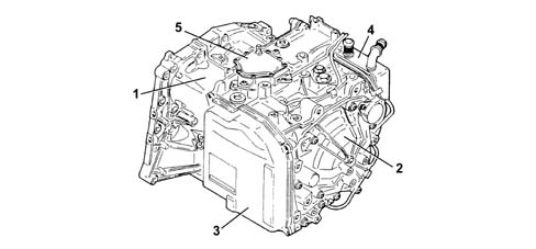
- 1 Torque converter casing
- 2 Gearbox casing and epicyclic gears
- 3 Hydraulic lock unit cover
- 4 Oil water heat exchanger
- 5 Multifunction switch
Safety
Engine start-up is possible only in PARKING (P) OR NEUTRAL (N) position. To avoid an untimely set-off due to involuntary action of the gear control lever, the automatic transmission is equipped with a Shift Lock that obliges the driver to press the driver to press the brake pedal to leave the parking position. The "foot+brake pedal" symbol on the selection grid reminds the driver of the obligatory procedure for leaving parking position.
Selection grid
The following positions are shown: parking (P), reverse (R),neutral (N), drive (D).
In the sequential system: + to shift up, - to shift down
Information to the driver
The driver is informed of the automatic transmission operating mode by means of a display that shows the following information:
- gear lever position,
- program selected by the driver,
- poorly-positioned gear lever (lever between two stable positions: the last stable position engaged flashes).
Advantages of the self-adaptive gearbox:
- 1st adapts to the driving system of each driver,
- 2nd in the case of steep descents: a normal gearbox shifts from 3rd to 4th when speed increases but with a self-adaptive transmission the computer registers the speed increase but also the fact that the accelerator pedal is raised and therefore uses the engine brake.
- 3rd during emergency braking: when the accelerator pedal is raised, the engine brake is activated in real time and does not allow a longer ratio. The gearbox shifts down as soon as the brake pedal is pressed.
OPERATION
Diagram showing information input/output between the NCA and AL4 automatic transmission control system sensors/actuators
The following diagram shows NCA input and output signals
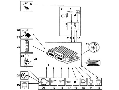
- 1 Automatic Transmission Node
- 2 Throttle position sensor
- 3 Engine speed sensor
- 4 Engine coolant temperature sensor
- 5 Engine Control Node
- 6 Accelerator pedal
- 7 Engine load signal
- 8 Engine speed and coolant temperature signal
- 9 Engine torque signal
- 10 Torque damping and dle speed compensation request
- 11 Gear selection warning lights
- 12 Tester input
- 13 EVS sequence solenoids
- 14 EVM pressure modulation solenoid
- 15 Exchanger by-pass solenoid
- 16 Gearbox oil temperature sensor
- 17 Gearbox oil pressure sensor
- 18 Gearbox input speed sensor
- 19 Gearbox output speed sensor
- 20 Multifunction switch
- 21 Reversing lights
- 22 Start-up lock relay
- 23 Actuator locking automatic transmission lever in position P
- 24 Selector lever
- 25 Program selector
- 26 Brake pedal
- 27 Brake light switch
Schematic cross-section through AL4 automatic transmission and differential
The following diagram shows a cross section through the gearbox with differential
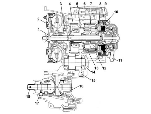
- 1 Drive input shaft
- 2 Torque converter
- 3 Oil pump
- 4 Brake F3
- 5 Central pinion PS2
- 6 Hydraulic lock
- 7 Brake F2
- 8 Brake F1
- 9 Clutch E2
- 10 Clutch E1
- 11 Input speed sensor
- 12 Gear set 2
- 13 Gear set 1
- 14 Intermediate shaft
- 15 Intermediate gear
- 16 Differential unit
- 17 Vehicle speed sensor
- 18 Drive output shaft
AL4 automatic transmission and differential operating diagram
The following figure shows the injection - ignition system operating diagram
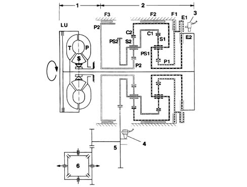
- 1 Torque converter
- LU - Lock-up clutch
- T - Converter turbine
- P - Converter pump
- S - Converter stator
- 2 Gear set assembly
- 3 Input speed sensor
- 4 Output speed sensor
- 5 Intermediate gear
- 6 Differential unit
- C1 - Gear set 1 crown wheel
- PS1 - Gear set 1 train carrier
- C2 - Gear set 2 crown wheel
- PS1 - Gear set 2 train carrier
- P1 - Gear set 1 differential gear
- P2 - Gear set 2 differential gear
- E1 - Clutch E1
- E2 - Clutch E2
- F1 - Brake F1
- F2 - Brake F2
- F3 - Brake F3
Main components of hydromechanical unit
Torque converter
The torque converter transmits power from the engine to the gearbox hydraulically and inceases torque when the vehicle is accelerating. Rotary motion is transmitted to the epicylic gear set via two propeller shafts:
- the crankshaft connected to the converter pump via the flywheel;
- the gearbox mainshaft that engages with the converter turbine hub.
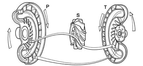
- P - Pump
- S - Stator
- T - Turbine
The converter consists of a pump P integral with the crankshaft, turbine t, integral with the gearbox mainshaft and stator S integral with the outer gear casing. The converter is full of fluid that allows transmission of drive torque due to the kinetic energy expended by the pump.
The torque converter is not subject to any type of wear because there is no mechanical link between the driven part and the drive part.
Impeller P is connected to the crankshaft and acts a pump when turned clockwise to transfer its energy to the fluid.
The centrifugal force pushes the fluid toward the outside of the impeller where it flows at high speed toward turbine T. Here the kinetic energy of the fluid imposes a clockwise rotary motion to the turbine. The fluid then passes through stator S, where it is diverted through an angle that allows it return to the pump with high efficiency. The stator is connected to the gear casing by means of a idler wheel engagement that prevents it turning anticlockwise and supplies a reaction torque proportional to the fluid flow diversion, which is added to that of the turbine.
The ratio between the torque acting on the turbine and the torque supplied by the pump is known as the torque multiplication ratio and is proportional to the difference in rotating speed between pump and turbine. When the wheels are still, the torque approximately double that delivered by the engine. As turbine speed increases, torque multiplication reduceds continuously and tends toward a 1:1 ratio. This corresponds to a turbine speed equal to 80-90% of pump speed. When turbine and pump speeds are almost the same, the stator is struck by an fluid flow that is angled to a degree that causes the direction of rotation to reverse. Because it is not locked by the idler wheel, it turns clockwise without impediment and the torque converter acts as an ordinary hydraulic coupling.
Lock-up clutch
A lock up clutch is a device that creates a mechanical link betwen the converter input and output when engaged, i.e. between the pump, integral with the crankshaft and the turbine, integral with the epicyclic gears.
When the lock up clutch is engaged, pump (P) and turbine (T) cease to slide in relation to one another to convert the gearbox into a manual transmission. This eliminates viscous friction loss in the torque converter.
This leads to a reduction in fuel consumption and the clutch slipping sensation typical of hydraulic transmissions that is caused by the difference between engine speed and vehicle speed.
Operation
Clutch released
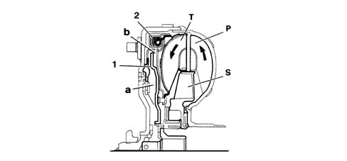
The fluid flowing inside the converter acts with the same pressure on the rear and front side of clutch engagement piston (1): turbine (T) is free to turn in relation to the cover of the converter, integral with pump (P).
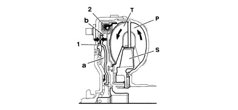
The NCA controls the EVM solenoid that brings about a pressure reduction at the rear so that piston (1) slides to lock the clutch. Turbine (T) is therefore connected to pump (P) and they cease to slide in relation to one another.
During speed shifts, the lock-up clutch is controlled in modulated manner. During this stage, pressure in the area is modulated in order to allow controlled slide between pump and turbine, which is very reduced.
Engine driver torque delivery irregularities are absorbed by a set of damping springs (2) arranged along the outside of the converter casing. These operate in a similar manner to ensure optimum driving comfort.
Epicyclic gear set
The gearbox offers five transmission ratios (four forward speeds and reverse) by means of two simple epicylic gear sets that are designated gear set 1 and gear set 2 respectively.
These gear sets are interconnected so that differential gear C1 is integral with gear train carrier PS2 and differential gear is integral with gear train carrier PS1. The various ratios are obtained by transmitting drive torque via certain parts of the assembly while locking others.
The torque input is via gear train carrier PS1, differential gear C1 or both, while the output is always from gear train carrier PS2.
Control elements
The gear set control elements comprise the brakes (that prevent a gear element and the outer casing from turning in relation to one another) and the clutches (that prevent two parts of the gear set from turning in relation to one another).
These are controlled to achieve four forward speeds and one reverse. They are locked hydraulically by oil under pressure and unlocked through the mechanical action of a cup spring that acts on the piston.
The oil bath operating system allows drive torque to be transmitted with practically no wear. these parts do not therefore require periodic adjustment.
The clutches are all multiplate type.
The brakes are all multiplate type (F1) or band type (F2) and (F3).
The following figure shows the layout and operation of gear control elements.
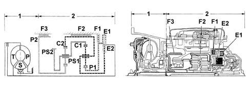
- 1 Torque converter unit
- 2 epicyclic gear assembly
- E1 - clutch E1 connects differential gear P1 to the gear input shaft
- E1 - clutch E2: connects gear train carrier PS1 to the gear input shaft
- F1 - brake F1: locks differential gear P1
- F2 - brake F2: locks crown wheel C2
- F3 - brake F3: locks differential gear P2
Operation - clutch
The clutches are all multiplate type.
They consist of a set of alternate steel plates (1) that are coated in friction material (2) and used on bell housing (3) and hub (4) respectively.
- clutch released (plates not transmitting torque) because there is no pressure in chamber (5), operating piston (6) is held back by return spring (7).
- clutch engaged (plates do not transmit torque) oil under pressure is sent via channel (8) connected to the control solenoid: the pressure causes the piston to move, overcome the spring pressure and compress the plates to prevent them turning in relation to one another.
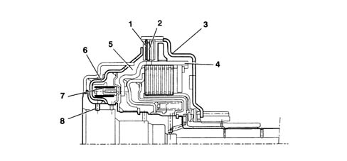
Operation - brakes
The multiplate brakes work in exactly the same way as the clutches. The band-type brakes consist of a steel band (1) that is wound on a drum (2) integral with the part of the gear set to be locked.
Brake released (the drum is not locked): since there is pressure in chamber (3), operating piston (4) is held back by return spring (5) so that there is clearance between band (1) and the drum.
Brake engaged (drum locked) oil under pressure is sent via a channel connected to the control solenoid: the pressure causes the piston to move, overcome the spring pressure and lock the drum to prevent it turning.
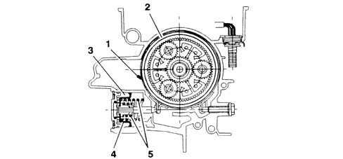
Parking lock ( shift-lock)
The gearbox is fitted with a shift-lock safety function to lock the vehicle. This operates by means of electromagnetic actuator (1) located in the selector lever turret and controlled by the NCA: when the actuator is not activated:
- the selector lever can be moved to position P;
- the lever cannot be moved from position P (vehicle locked).
The actuator is supplied in accordance with the following strategy:
- actuator not supplied with key OFF (engine off)
- actuator supplied with key ON and brake pedal operated.
Engine start-up is possible only with the selector lever in N or P position.
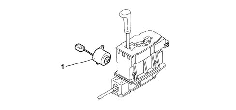
- 1 electromagnetic actuator
Oil pump
The oil pump is internal gear type. It is located between the torque converter and the gear casing and is driven directly by the converter pump impeller.
The oil pump performs the following functions:
- it supplies the necessary pressure to the hydraulic control system and gearbox control elements (clutches, brakes),
- it sends a fluid flow to the torque converter sheath to cool it down,
- it lubricates the mobile gearbox components,
- it makes fluid flow through the heat exchanger
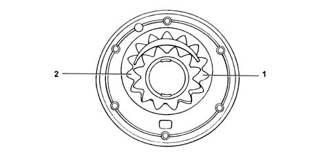
- 1 intake side
- 2 delivery side
DRIVE TRANSMISSION
The following diagrams show drive transmission under different operating conditions and indicate the control elements required to achieve the various transmission ratios. The following table summarises components activated on the basis of speed engaged and selector lever position.
| lever position | ratio engaged | lock-up clutch | E2 | F1 | F2 | F3 | EVS1 | EVS2 | EVS3 | EVS 4 | EVS 5 | EVS 6 |
|---|---|---|---|---|---|---|---|---|---|---|---|---|
| P | X | X | ||||||||||
| R | X | X | X | |||||||||
| N | X | X | ||||||||||
| D | 4 | X | X | X | X | |||||||
| D | 3 | X(*) | X | |||||||||
| D | 2 | X(*) | X | X | X | X | ||||||
| D | 1 | X | X | X | ||||||||
| +/_ | 3 | X(*) | X | |||||||||
| +/_ | 2 | X(*) | X | X | X | X | X | |||||
| +/_ | 1 | X | X | X | ||||||||
| +/_ | 2 | X(*) | X | X | X | X | ||||||
| +/_ | 1 | X(*) | X | X | X | |||||||
| +/_ | 1 | X | X | X |
Neutral: (selector lever in position N)
All the clutches and brakes are disengaged, drive is not therefore transmitted to the epicyclic gears and thus to the output shaft.
The lock-up is off and the vehicle can therefore move if on a slope.
Parking: (selector lever in position P)
All clutches and brakes are disengaged: the parking lock is also engaged and this prevents the vehicle from moving.
First speed
Drive torque is transmitted via the torque converter (or from the lock-up brake according to the conditions) and clutch E1 to differential gear PI and, via planet wheel SI to outer ring gear C1 that is integral with gear train carrier PS2. Because differential gear P2 is locked by brake F3, planet wheels S2 turn on it to drive gear train carrier PS2 and thus output pinion.
| lock-up clutch | clutch E1 | clutch E2 | brake F1 | brake F2 | brake F3 |
|---|---|---|---|---|---|
| free or locked | locked | free | free | free | locked |
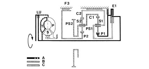
- A - engine element
- B - driven element
- C - locked element
Second speed
Drive torque is transmitted via the torque converter (or, according to conditions, from the lock-up clutch) and clutch E2 to gear train carrier PS1, integral with ring gear C2.
Because differential gear P2 is locked by brake F3, ring gear C2 turns planet wheels S2 on it to drive gear train carrier PS2 and thus output pinion.
| lock-up clutch | clutch E1 | clutch E2 | brake F1 | brake F2 | brake F3 |
|---|---|---|---|---|---|
| free or locked | free | locked | free | free | locked |
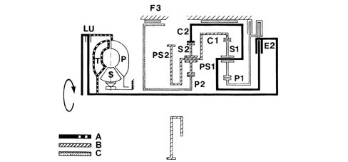
- A - engine element
- B - driven element
- C - locked element
Third speed
Drive torque is transmitted via the torque converter (or, according to conditions, from the lock-up clutch) to both clutches E1 and E2. Because these are locked, both gears (and thus the output pinion) turn locked together at the same speed.
| lock-up clutch | clutch E1 | clutch E2 | brake F1 | brake F2 | brake F3 |
|---|---|---|---|---|---|
| free or locked | locked | locked | free | free | free |
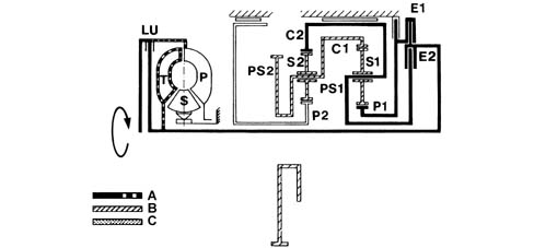
- A - engine element
- B - driven element
- C - locked element
Fourth speed
Drive torque is transmitted via the torque converter (or, according to conditions, from the lock-up clutch) and clutch E2 to gear train carrier PS1, integral with ring gear C2.
Because differential gear P1 is locked by brake F1, planet wheels S1 turn on it to drive ring gear C1 that is integral with gear train carrier PS2 and thus output pinion.
| lock-up clutch | clutch E1 | clutch E2 | brake F1 | brake F2 | brake F3 |
|---|---|---|---|---|---|
| free or locked | free | locked | locked | free | free |
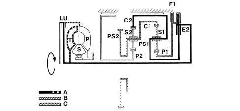
- A - engine element
- B - driven element
- C - locked element
Reverse gear
Drive torque is transmitted via the torque converter and clutch E1 to differential gear P1 that turns planet wheels S1. Because gear train carrier PS1 is locked by brake F2, planet wheels S1 drive ring gear C1 and thus the output pinion in the opposite direction to differential wheel P1.
| lock-up clutch | clutch E1 | clutch E2 | brake F1 | brake F2 | brake F3 |
|---|---|---|---|---|---|
| free or locked | locked | free | free | locked | free |
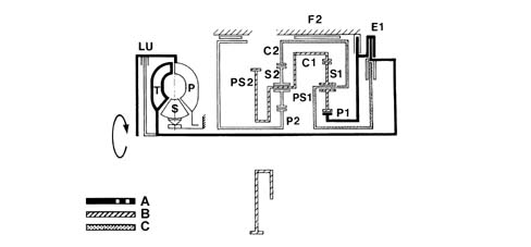
- A - engine element
- B - driven element
- C - locked element
MAIN COMPONENTS OF ELECTROHYDRAULIC UNIT
Hydraulic lock
The hydraulic lock is supplied by the oil pump at a given internal pressure (known as line pressure) and contains the hydraulic circuits and valves supplying the brakes and/or clutches, the lock-up clutch and lubrication and a hydraulic accumulator. It also houses all the solenoids required for clutch operation.
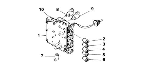
- 1 hydraulic lock
- 2 EVS4 sequence solenoid
- 3 EVS3 sequence solenoid
- 4 EVS1 sequence solenoid
- 5 EVS2 sequence solenoid
- 6 EVS4 sequence solenoid
- 7 EVS5 sequence solenoid
- 8 line pressure modulation solenoid (EVM1)
- 9 lock-up clutch engagement modulation solenoid (EVM2)
- 10 manual solenoid (VM)
Operation - gear change
Pressure changes applied during a gear change from 3rd to 4th are described as an example. A. clutch release E1:
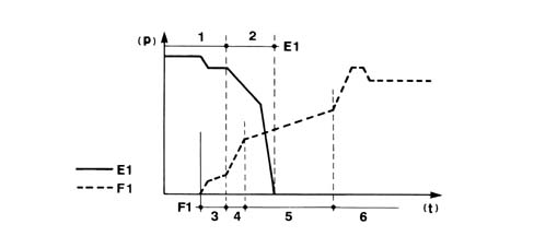
- 1 pressure maintenance stage;
- 2 gradual pressure discharge stage in piston B: engagement of brake F1;
- 3 rapid piston filling stage;
- 4 rapid pressure increase stage (approach);
- 5 slow pressure increase stage (engagement);
- 6 confirmation and maintenance stage;
- p - pressure
- t - time
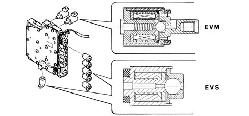
Hydraulic pressure modulation solenoid (EVM)
This solenoid modujlates oil pressure in the control circuits according to gearbox working conditions.
Pressure may be modulated continuously:
- from 3 bars to 12 bars during gear changes, in a manner directly proportional to the drive torque to be transmitted;
- from 12 bars to 21 bars during take-off from a standing start.
This modulation is made possible by a pressure accumulator inside the lock. This allows the lock to act on the control elements by an amount proportional to the torque to which they are subject. This makes gear changes (EVM1) or lock-up clutch engagement (EVM2) smoother at low loads.
A pressure value reads the pressure.
The solenoid is controlled through its duty-cycle to earth by the NCA and supplies a pressure proportional to the effective supply voltage.
Sequence solenoid (EVS)
When excited, these solenoids supply the hydraulic valves in the hydraulic lock to send fluid under pressure to the required control components.
The solenoid is turned on-off to earth by the NCA.
Heat exchanger and by-pass solenoid
Oil-water heat exchanger (1) cools the fluid. By-pass solenoid (2) controls the flow of fluid to the exchanger according to fluid temperature and engine speed. More specifically, the solenoid opens if:
- the gearbox fluid temperature exceeds a certain threshold that is partly dependent on the speed engaged.
- the engine speed exceeds a given threshold. When the solenoid is closed, minimal fluid flows to the heat exchanger. The solenoid is turned on-off to earth by the NCA.
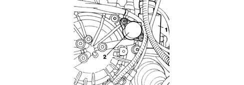
BASIC COMPONENTS OF THE CONTROL UNIT
Automatic Gearbox Node/connector pin-out
The following figure shows the Automatic Gearbox Node connector pinout
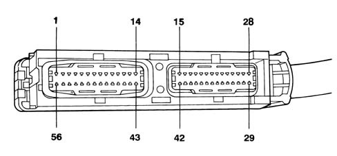
| Pin | Function |
|---|---|
| 1 | Sequential solenoid power supply |
| 2 | exchanger by-pass solenoid power supply |
| 3 | Not used |
| 4 | Instrument panel |
| 5 | Torque damping and idle speed compensation request |
| 6 | OBD signal |
| 7 | EVS3 sequence solenoid earth |
| 8 | EVS4 sequence solenoid earth |
| 9 | EVS2 sequence solenoid earth |
| 10 | EVS1 sequence solenoid earth |
| 11 | Lock actuator control in position P (shift-lock) |
| 12 | Exchanger fluid flow solenoid control |
| 13 | EVS5 sequence solenoid earth |
| 14 | EVS6 sequence solenoid earth |
| 15 | Not used |
| 16 | Brake light switch signal (low active) |
| 17 | Diagnostic tester line L |
| 18 | Diagnostic tester line K |
| 19 | Lock-up clutch engagement modulation solenoid EVM2 |
| 20 | Line pressure modulation solenoid EVM1 |
| 21 | Not used |
| 22 | Engine torque signal |
| 23 | Engine load signal |
| 24 | Oil pressure sensor power supply (+) |
| 25 | Oil pressure sensor power supply (-) |
| 26 | Modulation solenoid power supply (EVM) |
| 27 | NCA power supply |
| 28 | NCA earth |
| 29 | CAN |
| 30 | CAN |
| 31 | Multifunction switch position contact S2 |
| 32 | Multifunction switch contact S3 |
| 33 | Multifunction switch contact S4 |
| 34 | Multifunction switch contact P/N |
| 35 | Not used |
| 36 | Signal for program selector in position 1 |
| 37 | Multifunction switch contact S1 |
| 38 | Not used |
| 39 | Not used |
| 40 | Signal for program selector in snow position |
| 41 | Signal for program selector in normal/sport position |
| 42 | Multifunction switch earth |
| 43 | Brake light switch signal (high active) |
| 44 | Accelerator pedal raised switch |
| 45 | Input speed sensor signal (+). |
| 46 | Input speed sensor signal (-). |
| 47 | Output speed sensor signal (+). |
| 48 | Output speed sensor signal (-). |
| 49 | Engine speed signal |
| 50 | Not used |
| 51 | Not used |
| 52 | Not used |
| 53 | Fluid temperature signal (-) |
| 54 | Fluid temperature signal (+) |
| 55 | Fluid pressure sensor power signal |
| 56 | Throttle position sensor signal |
Interface module - connector coding
The following figure shows the interface module
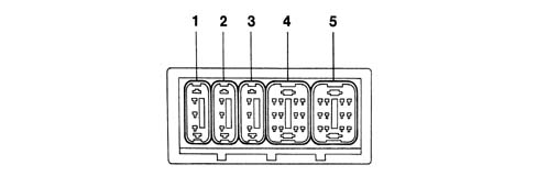
| pos. | colour | pin no. | function |
|---|---|---|---|
| 1 | blue | 3 | gearbox water-oil exchanger by-pass solenoid |
| 2 | yellow | 3 | gearbox input speed sensor |
| 3 | green | 3 | Fluid pressure sensor |
| 4 | yellow | 12 | transmission fluid hydraulic and temperature lock |
| 5 | green | 12 | multifunction switch |
OPERATION
The gearbox can work in two modes:
- fully automatic,
- manual.
Fully automatic operation (selector in position D)
In this situation, the control system manages gear changes (engagement of higher gears) or downward gear shifts (engagement of lower gear) as a result of certain actions or situations, in particular: it engages a higher speed if:
- the driver presses the accelerator pedal and the vehicle accelerates
- the driver releases the accelerator pedal after kick-down
- resistant torque falls while driving
- the driving style learnt by the system is changed (less sporty)
the speed engaged is maintained:
- if the accelerator pedal is released rapidly
- throughout the release stroke
it engages a lower speed if:
- if the driver makes a kick-down manoeuvre
- the driver presses the brake pedal
- resistant torque increases while driving
- the driving style learnt by the system is changed (more sporty)
Manual operation (Selector in +/- position)
The driver can change speed by moving the selector lever up (+, gear change) or down (- downward shift).
The system naturally maintains all control settings required to safeguard and protect the gearbox and engine from incorrect manoeuvres.
the system notifies the driver that vehicle driving conditions will not allow engagement of the selected speed by making a warning light on the dashboard flash.
Gear shift laws
The gearbox control system determines whether or not to implement the lock-up clutch automatically and thus shift through the various speeds in accordance with certain stored objectives.
The system decides whether or not to shift from one speed to another on the basis of a set of shift laws stored in the node.
Each shift law consists a set of curves calculated on the basis of two parameters:
- accelerator pedal position;
- Vehicle speed.
Each gear shift law contains:
- upward (shift up) and downward (shift down) shift curves for all speeds;
- lock-up clutch engagement and release curves;
- kick-down intervention points.
The following figure shows an example of a gear shift law.
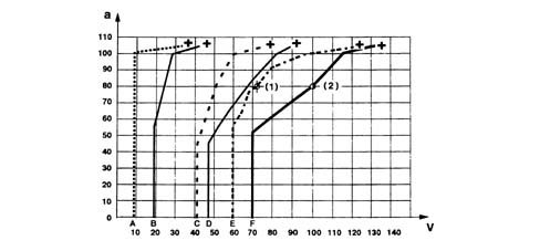
- v - vehicle speed (km/h)
- a - accelerator pedal position (%)
- (1) - example 1
- (2) - example 2
- A - shift 2-1
- B - shift 1-2
- C - shift 3-2
- D - shift 2-3
- E - shift 3-4
- F - shift 4-3
- + - kick-down points
Any gearbox service point can be identified by means of two parameters:
- accelerator pedal position;
- Vehicle speed.
When the gearbox instantaneous service point intersects a curve, the system makes the gear shift associated with the intersected curve.
When speed is increasing, the upward shift curve is naturally considered (gear change), while the downward shift curve (shift down) is considered when the speed decreases.
Example 1:
- accelerator pedal pressed through 80% of its travel;
- ratio engaged: 3rd speed;
- the gearbox shifts from 3rd to 4th as soon as speed increases to 100 km/h.
Example 2:
- accelerator pedal pressed through 80% of its travel;
- ratio engaged: 4th speed;
- the gearbox shifts from 4th to 3rd as soon as speed increases to 72 km/h.
the same principle applies for lock-up clutch engagement/release curves.
Management strategies
Management strategies must identify the shift law best suited to the contingent vehicle operating situation. It must also implement a set of actions in specific cases.
The main gearbox management strategies are as follows:
- self-adaptive strategies (normal service conditions);
- sport strategy (high-performance service conditions);
- snow strategy (low ground grip conditions);
- lock-up clutch lock inhibition strategy (start-up or overheated clutch);
- warm-up strategy;
- gearbox thermal protection strategy (transmission fluid overheated).
Self-adaptive strategies
These are the strategies normally used by the system, which is able to learn external conditions (vehicle and driver) and adapt gear shifts accordingly. Six different speed shift laws may be identified:
- three laws determined by driver behaviour
- three laws determined by vehicle conditions.
The three laws determined by driver behaviour are as follows: ECO law, MEDIUM law, SPORT law.
These are mainly determined on the basis of the following parameters:
- throttle position;
- throttle movement speed;
- average throttle position within a certain time range;
- gearbox output speed changes.
The laws determined by vehicle conditions are as follows: BRAKING 1 law, BRAKING 2 law, DESCENT law. These are mainly determined on the basis of the following parameters:
- throttle position;
- vehicle acceleration;
- Vehicle speed.
The NCA selects the most appropriate point according to a strategy that is roughly summarised in the following table.
| driving conditions | vehicle driving conditions | |||
|---|---|---|---|---|
| descent | flat | slight hill | steep hill | |
| normal | DESCENT | ECO | BRAKING 1 | BRAKING 2 |
| lively | DESCENT | MEDIUM | BRAKING 1 | BRAKING 2 |
| sporty | SPORT | SPORT | SPORT | BRAKING 2 |
The self-adaptive strategies also feature certain operating details:
- gear shift inhibition when the accelerator is released quickly: this function prevents the gearbox shifting to a higher speed when the accelerator is released to maintain the engine brake effect. It is also enabled with DESCENT shift laws when the accelerator is released.
- temporary increase in sportiness: if the system suddenly detects accelerator pedal movement, a shift law that is sportier from the current law is temporarily selected - from the driver-determined selection - (i.e. from ECO to MEDIUM or from MEDIUM to SPORT);
- downward shifting during braking: the system can detect braking intensity by assessing vehicle deceleration. The shortest ratio compatible with instantaneous driving conditions is therefore engaged to achieve maximum engine braking effect.
Snow strategy
This is activated by pressing the relevant button.
The following operating features are displayed:
- selector in position D;
- 1st speed engagement inhibition;
- more widely-spaced gear ratios;
- enablement of kick-down only for speeds below 15 km/h;
- compulsory shift to lower speed when brake pedal operated.
Lock-up clutch lock strategy
This strategy involves torque converter operation with the lock-up clutch off. It is activated under the following conditions:
- with transmission fluid temperature lower than 0°C upon start-up to promote fluid heating;
- when the lock-up clutch overheats (determined by means of NCA software, mainly on the basis of engine load, number of engagements/releases over a period and the current shift law);
- in the case of lock-up clutch failure.
Warm-up strategy
The warm-up strategy helps the catalytic converter warm up faster and is implemented under the following conditions:
- transmission fluid temperature between 15°C and 30°C upon start-up;
- at the end of the lock-up clutch lock strategy.
The strategy lasts for a timed period that depends on the vehicle engine type.
Gearbox thermal protection strategies
The transmission fluid high temperature safety program is automatically selected with transmission fluid temperatures higher than 120°C and is maintained until the temperature drops below 110°C. While this program is active, specific functions are introduced that can inhibit upward or downward gear changes and keep the lock-up clutch engaged for longer than normal to ensure fluid cooling.
interface with Engine Control Node
The engine control and gearbox control systems communicate with one another to optimise vehicle operation.
a) from engine control to gearbox control:
- throttle position information: it is used mainly to detect idling and over-run situations and also manage the kick-down function,
- engine speed information: this is mainly used to determine the torque converter slide stage (comparison with gearbox input signal) and manage protection and gear shift strategies,
- drive torque information (engine load): this is used mainly to determine line pressure and manage gear shift strategies,
b) from gearbox control to engine control:
- torque reduction request: used to ensure smoother shifts,
- multifunction switch information: used to establish engine idle speed under the various gearbox conditions with the vehicle at a standstill.
Device for determining fluid wear level
The system is fitted with a counter that is increased whenever the Automatic Transmission Node is supplied electrically.
The counter can count up to 32768 units (32kbytes) corresponding to about 6000 hours of operation with fluid temperature at 95 °C.
The counter is further increased, for the same time period, on the basis of fluid temperature to take into account the extra ageing caused by the high temperatures.
When the counter is full, the snow and sport warning lights flash simultaneously.
The value memorized by the counter can be changed, in the following cases, using the EXAMINER in the specific section for the gearbox:
1) Replacing the automatic transmission
In this case the calculator must be completely zeroed
2) Replacing the calculator
In this case it is vital to make a note of the value of the old counter and rememorize it in the new one
3) Adding new oil
In this case for every half litre of new oil added, remove 2750 units from the value memorized in the counter
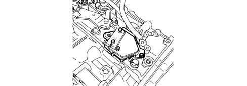
Multifunction switch
The switch is coaxial with the gear selection axle connected to the selector lever. It performs the following functions:
- it displays lever position on the instrument panel;
- engine start-up is possible only if the lever is in P or N position;
- it allows the reversing lights to come on with the lever in position R.
Gearbox input speed sensor (a) Gearbox output speed sensor (b)
The sensor takes the form of a tubular case containing a permanent magnet and an electrical winding.
As the toothed wheel passes the winding, voltage changes are set up at the winding terminals due to the changing gap: this change generates a sinusoidal signal at the connector terminals, with signal frequency proportional to toothed wheel speed.
the input speed signal is used mainly to:
- determined converter slide (with lock-up clutch released);
- determine gear shifting.
The output speed signal is used mainly to:
- determine brake and clutch sliding during speed shifts;
- determine gear shifts;
- carry out self-adaptivity actions.
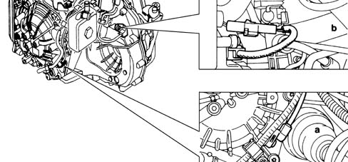
- a - gearbox input speed sensor
- b - gearbox output speed sensor
Oil temperature sensor
The sensor consists of an NTC resistance element (Negative temperature coefficient) whose electrical resistance falls as temperature increases.
The fluid temperature signal is used mainly to:
- Correct line pressure;
- enable specific strategies in the case of high fluid temperatures;
- modulate lock-up clutch intervention management.

Oil pressure sensor
The sensor consists of a resistance bridge screen-printed onto a flexible membrane that separates the measurement chamber (connected to the environment to be measured) and the reference chamber. Membrane shape changes due to the pressure difference between chambers alters bridge resistance and thus output voltage because the supply voltage remains constant.
The fluid pressure signal is used mainly to:
- manage line pressure changes.

DIAGNOSTICS
Self-diagnostic function
The Automatic Gearbox Node is equipped with the following self-diagnostic function. This constantly monitors the sensors and actuators in order to detect faults and malfunctions: these errors are stored and may be read using diagnostic equipment. The following functions are monitored:
- NCA
- NCA power supply
- oil pressure sensor - circuit open
- sequential solenoid power supply EVS
- line pressure regulation circuit
- multifunction switch
- operation of line pressure modulation solenoid EVM1
- operation of lock-up clutch engagement modulation solenoid EVM2
- heat exchanger fluid by-pass solenoid
- manual solenoid VM
- accelerator pedal positon not stored
- gearbox input speed sensor
- gearbox output speed sensor
- engine speed information
- analogue sensor power supply
The system informs the driver of the presence of an error by flashing a warning light on the dashboard.
Recovery function
When a fault is detected, the system activates certain hydraulic and mechanical safety strategies to ensure the gearbox operates under safe conditions. The system assesses the extend of the fault and allows the vehicle to be driven if possible.
Recovery functions are available for certain fault types. These minimise the loss of gearbox performance by imposing a series of gradually reducing gearbox function levels.
| level | fault (i) present (i) | observed effect |
|---|---|---|
| 1 | - Transmission fluid temperature | Slight reduction in performance, effect on driving comfort |
| - Drive torque information | ||
| - Instrument control | ||
| - Selector lever lock actuator | ||
| 2 | - Vehicle speed | Great reduction in gearbox performance (speed shift quailty less good, loss of functions) |
| - Lock-up clutch engagement modulation solenoid | ||
| - Converter | ||
| - Torque damping output | ||
| - Fluid pressure sensor | ||
| - Sensor supply fault | ||
| - Brake light switch | ||
| - Exchanger by-pass solenoid | ||
| - Throttle position signal and missing torque signal | ||
| 3 | - Engine speed | Great reduction in gearbox performance (loss of functions, reduced functions) |
| - Gearbox input speed sensor | ||
| 4 | - Throttle position sensor information | Change to 3rd speed the next time the contact is activated if the vehicle is in third speed, maintenance of speed and automatic engagement of 3rd speed the next time the contact is activated (this reduced mode is known as escape mode: permitted top speed (100 km/h) |
| - Drive torque information | ||
| - Multifunction switch loss of reversing safety during motion | ||
| - Analogue sensor power supply | ||
| - Line pressure modulation solenoid EVM1 | ||
| - Main pressure regulation | ||
| - Exchanger by-pass solenoid control | ||
| - Gearbox input and output speed | ||
| - Engine input and output speed | ||
| - Engine input and output speed | ||
| 5 | - Automatic transmission mode inactive | Hydraulic shift to 3ed (this reduced mode is known as escape mode: permitted top speed 100 km/h) |
| - Sequential solenoids | ||
| - Sequential solenoid power supply | ||
| - Accelerator pedal position not learnt |
Parts & tools for this job For 2002 Fiat Ulysse
- PARTTransmission filter kitSearch: Fiat Ulysse 2002 transmission filter kit
- FLUIDAutomatic transmission fluidSearch: Fiat automatic transmission fluid
- TOOLFluid transfer pumpSearch: fluid transfer pump
Links open Amazon search results in a new tab. As an Amazon Associate I earn from qualifying purchases.