| PINPOINT TEST A : REVERSING LAMPS ARE INOPERATIVE |
| TEST CONDITIONS | DETAILS/RESULTS/ACTIONS |
| A1: CHECK FUSE F84 (10 A) (CJB). |
| | 1 Ignition switch in position 0. |
| | 2 Disconnect fuse F84 (10 A) (CJB). |
| | 3 CHECK fuse F84 (10 A) (CJB). |
| | Is the fuse OK? Yes No RENEW fuse F84 (10 A) (CJB) and CHECK the operation of the system. If the fuse blows again, LOCATE and RECTIFY the short to ground using the Wiring Diagrams. CHECK the operation of the system. |
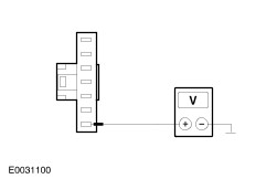
| A2: CHECK THE VOLTAGE SUPPLY TO FUSE F84 (10 A) (CJB) FOR OPEN CIRCUIT |
| | 1 Connect Fuse F84 (10 A) (CJB). |
| | 2 Ignition switch in position II. |
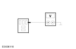
| | 3 Measure the voltage between fuse F84 (10 A) (CJB) and ground. |
| | Is battery voltage measured? Yes No LOCATE AND RECTIFY the break in the voltage supply of fuse F84 (10 A) (CJB) using the Wiring Diagrams. If necessary RENEW the CJB. CHECK the operation of the system. |
| A3: DETERMINE MODEL VERSION |
| | 1 Determine the model version. |
| | Does the vehicle have an automatic transmission? Yes No |
| A4: CHECK THE EQUIPMENT LEVEL |
| | 1 Compare the following systems with the equipment level of the vehicle: - Double locking
- Footwell lamps
- Map lights
- Alarm
- Headlamp switch-off delay
|
| | Is the vehicle equipped with one of the above systems? Yes Vehicles with high equipment level: GO to A9. No Vehicles with low equipment level: GO to A5. |
| A5: CHECK VOLTAGE SUPPLY TO THE REVERSING LAMP SWITCH FOR OPEN CIRCUIT |
| | 1 Ignition switch in position 0. |
| | 2 Disconnect Reversing lamp switch from connector. - MTX/MMT6: Transmission C864
|
| | 3 Ignition switch in position II. |
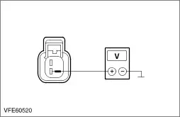
| | 4 Measure the voltage between the reversing lamp switch: - MTX/MMT6 transmission, vehicles built before 04/2005: Connector C864, pin 2, circuit 15-LG28 (GN/WH), wiring harness side and ground.
- IB5 transmission, vehicles built before 04/2005: Connector C866, pin 2, circuit 15-LG28 (GN/WH), wiring harness side and ground.
|
| | 5 MTX/MMT6 transmission, vehicles built from 04/2005: Measure the voltage between the reversing lamp switch, connector C864, pin 2, circuit 15-LG28 (GN/WH), wiring harness side and ground. |
| | 6 IB5 transmission, vehicles built from 04/2005: Measure the voltage between the reversing lamp switch, connector C866, pin 2, circuit 15-LG28 (GN/WH), wiring harness side and ground. |
| | Is battery voltage measured? Yes No - Vehicles with low equipment level: GO to A6. - Vehicles with high equipment level: LOCATE and RECTIFY the break in the circuit between the reversing lamp relay, pin 3 and the reversing lamp switch using the Wiring Diagrams. CHECK the operation of the system. |
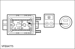
| A6: CHECK CIRCUIT 15-LG28(A) (GN/WH) BETWEEN THE CJB AND THE REVERSING LAMP SWITCH FOR OPEN CIRCUIT |
| | 1 Ignition switch in position 0. |
| | 2 Disconnect CJB from connector C96. |
| | 3 Measure the resistance between CJB: - MTX/MMT6 transmission, vehicles built before 04/2005: Connector C96, pin 33, circuit 15-LG28A (GN/WH), wiring harness side and the reversing lamp switch, connector C864, pin 2, circuit 15-LG28 (GN/WH), wiring harness side.
- IB5 transmission, vehicles built before 04/2005: Connector C96, pin 33, circuit 15-LG28A (GN/WH), wiring harness side and the reversing lamp switch, connector C866, pin 2, circuit 15-LG28 (GN/WH), wiring harness side.
|
| | 4 MTX/MMT6 transmission, vehicles built from 04/2005: Measure the resistance between the CJB, connector C96, pin 33, circuit 15-LG28A (GN/WH), wiring harness side and the reversing lamp switch, connector C864, pin 2, circuit 15-LG28 (GN/WH), wiring harness side. |
| | 5 IB5 transmission, vehicles built from 04/2005: Measure the resistance between the CJB, connector C96, pin 33, circuit 15-LG28A (GN/WH), wiring harness side and the reversing lamp switch, connector C866, pin 2, circuit 15-LG28 (GN/WH), wiring harness side. |
| | Is a resistance of less than 2 Ohms registered? Yes RENEW the CJB. CHECK the operation of the system. No Vehicles with low equipment level or vehicles with M66 transmission: LOCATE and RECTIFY the break in the circuit between the CJB and the reversing lamp switch with the aid of the Wiring Diagrams. CHECK the operation of the system. |
| A7: CHECK THE REVERSING LAMP SWITCH |
| | 1 Ignition switch in position 0. |
| | 2 Fused bridging cable (10A) at the reversing lamp switch - MTX/MMT6 transmission, vehicles built before 04/2005: Connect connector C864 between pin 2, circuit 15-LG28 (GN/WH) and pin 1, circuit 15S-LG9(A) (GN/BK), wiring harness side.
- IB5 transmission, vehicles built before 04/2005: Connect connector C866 between pin 2, circuit 15-LG28 (GN/WH) and pin 1, circuit 15S-LG9(A) (GN/BK), wiring harness side.
|
| | 3 MTX/MMT6 transmission, vehicles built from 04/2005: Connect a fused bridging cable (10 A) at the reversing lamp switch, connector C864 between pin 2, circuit 15-LG28 (GN/WH) and pin 1, circuit 15S-LG9(A) (GN/BK), wiring harness side. |
| | 4 IB5 transmission, vehicles built from 04/2005: Connect a fused bridging cable (10 A) at the reversing lamp switch, connector C866 between pin 2, circuit 15-LG28 (GN/WH) and pin 1, circuit 15S-LG9(A) (GN/BK), wiring harness side. |
| | 5 Ignition switch in position II. |
| | 6 CHECK the operation of the reversing lamps. |
| | Do the reversing lamps illuminate? Yes INSTALL A NEW reversing lamp switch. CHECK the operation of the system. No - Vehicles with high equipment level: GO to A8. - Vehicles with low equipment level: GO to A14. |
| A8: CHECK CIRCUIT 15S-LG9 (GN/BK) FOR OPEN CIRCUIT |
NOTE:All model variants: The fused jumper lead used in the previous test step is still connected to the reversing lamp switch. |
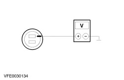
| | 1 Measure the voltage between the reversing lamp relay, socket C1003, pin 5, circuit 15-LG46 (GN/OG) and 15S-LG9 (GN/BK), BJB side and ground. |
| | Is battery voltage measured? Yes No LOCATE and RECTIFY the break in the circuit between the reversing lamp switch and the reversing lamp relay using the Wiring Diagrams. CHECK the operation of the system. |
| A9: CHECK THE VOLTAGE AT THE POWER CIRCUIT OF THE REVERSING LAMP RELAY |
| | 1 Ignition switch in position 0. |
| | 2 Disconnect Only vehicles with automatic transmission: Reversing lamp relay from socket C1003. |
| | 3 Ignition switch in position II. |
| | 4 Measure the voltage between the reversing lamp relay, socket C1003, pin 3, circuit 15-LG46 (GN/OG)/15-LG28 (GN/WH), wiring harness side and ground. |
| | Is battery voltage measured? Yes - Manual transmission, vehicles with high equipment level: GO to A5. No |
| A10: CHECK CIRCUIT 15-LG46 (GN/OG) BETWEEN THE CJB AND THE REVERSING LAMP RELAY FOR OPEN CIRCUIT |
| | 1 Ignition switch in position 0. |
| | 2 Disconnect CJB from connector C96. |
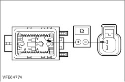
| | 3 Measure the resistance between the CJB, connector C96, pin 33, circuit 15-LG46 (GN/OG), wiring harness side and the reversing lamp relay, socket C1003, pin 3, circuit 15-LG46 (GN/OG)/15-LG28 (GN/WH), BJB side. |
| | Is a resistance of less than 2 Ohms registered? Yes RENEW the CJB. CHECK the operation of the system. No LOCATE and RECTIFY the break in the circuit between the CJB and the reversing lamp relay with the aid of the Wiring Diagrams. CHECK the operation of the system. |
| A11: CHECK THE VOLTAGE AT THE CONTROL CIRCUIT OF THE REVERSING LAMP RELAY |
| | 1 Measure the voltage between the reversing lamp relay, socket C1003, pin 1, circuit 15-LG45 (GN/BK), BJB side and ground. |
| | Is battery voltage measured? Yes No LOCATE and RECTIFY the break in the circuit between soldered connection S164 and the reversing lamp relay using the Wiring Diagrams. CHECK the operation of the system. |
| A12: CHECK REVERSING LAMP RELAY |
| | 1 Ignition switch in position 0. |
| | 2 Connect a fused jumper wire (10 A) at the reversing lamp relay, socket C1003, between pin 3, circuit 15-LG46 (GN/OG)/15-LG28 (GN/WH) and pin 5, circuit 15S-LG46 (GN/OG)/15S-LG9 (GN/BK), BJB side. |
| | 3 Ignition switch in position II. |
| | 4 CHECK the operation of the reversing lamps. |
| | Do the reversing lamps illuminate? Yes No |
| A13: CHECK THE CONTROL CIRCUIT 91S-LG45 (BK/GN) OF THE REVERSING LAMP RELAY FOR OPEN CIRCUIT |
| | 1 Ignition switch in position 0. |
| | 2 Disconnect Transmission control unit (TCU). - Vehicles with automatic transmission (CFT23): from connector C812
- Vehicles with 4-speed automatic transmission: from connector C414
|
| | 3 Measure the resistance between the reversing lamp relay, socket C1003, pin 2, circuit 91S-LG45 (BK/GN), BJB side and: - Vehicles with automatic transmission (CFT23): Transmission control unit (TCU), connector C812, pin 15, circuit 91S-LG45 (BK/GN), wiring harness side.
- Vehicles with 4-speed automatic transmission: Transmission control unit (TCU), connector C414, pin 67, circuit 91S-LG45 (BK/GN), wiring harness side.
|
| | Is a resistance of less than 2 Ohms registered? Yes - Vehicles with automatic transmission (CFT23): CHECK the reversing lamp relay according to the component test at the end of this section and RENEW as necessary. CHECK the operation of the system. If the relay is OK:
REFER to: Diagnostics (307-01A Automatic Transmission/Transaxle - Vehicles With: Automatic Transmission (CFT23), Diagnosis and Testing).
- Vehicles with 4-speed automatic transmission: CHECK the reversing lamp relay according to the component test at the end of this section and RENEW as necessary. CHECK the operation of the system. If the relay is OK:
REFER to: Diagnostics (307-01A Automatic Transmission/Transaxle - Vehicles With: Automatic Transmission (CFT23), Diagnosis and Testing).
No LOCATE and RECTIFY the break in the circuit between the reversing lamp relay and transmission control unit using the Wiring Diagrams. CHECK the operation of the system. |
| A14: CHECK FOR OPEN CIRCUIT IN 15S-LG9(A) (GN/BK), OR 15S-LG46 (GN/OG) |
| | 1 Ignition switch in position 0. |
| | 2 Disconnect CJB from connector C96. |
| | 3 Measure the resistance between: - Manual transmission, vehicles with low equipment level, vehicles built before 04/2005: Reversing lamp switch, connector C864, between pin 1, circuit 15S-LG9(A) (GN/BK) and the CJB, connector C96, pin 25, circuit 15S-LG9A (GN/BK), wiring harness side.
- Manual transmission, vehicles with low equipment level, vehicles built before 04/2005: Reversing lamp switch, connector C866, between pin 1, circuit 15S-LG9(A) (GN/BK) and the CJB, connector C96, pin 25, circuit 15S-LG9A (GN/BK), wiring harness side.
- Manual transmission, vehicles with high equipment level: Reversing lamp relay, socket C1003, between pin 5, circuit 15S-LG46 (GN/OG)/15S-LG9 (GN/BK), BJB side and the CJB, connector C96, pin 25, circuit 15S-LG46 (GN/OG), wiring harness side.
- Automatic Transmission: Reversing lamp relay, socket C1003, between pin 5, circuit 15S-LG46 (GN/OG)/15S-LG9 (GN/BK), BJB side and the CJB, connector C96, pin 25, circuit 15S-LG46 (GN/OG), wiring harness side.
|
| | 4 Manual transmission, vehicles with low equipment level, vehicles built from 04/2005: Measure the resistance between the reversing lamp switch, connector C864, between pin 1, circuit 15S-LG9(A) (GN/BK) and the CJB, connector C96, pin 25, circuit 15S-LG9A (GN/BK), wiring harness side. |
| | 5 IB5 transmission, vehicles built from 04/2005: Measure the resistance between the reversing lamp switch, connector C866, between pin 1, circuit 15S-LG9(A) (GN/BK) and the CJB, connector C96, pin 25, circuit 15S-LG9A (GN/BK), wiring harness side. |
| | Is a resistance of less than 2 Ohms registered? Yes No - Manual transmission, vehicles with low equipment level: LOCATE and RECTIFY the break in the circuit between the reversing lamp switch and the CJB using the Wiring Diagrams. CHECK the operation of the system. - Manual transmission, vehicles with high equipment level: LOCATE and RECTIFY the break in the circuit between the reversing lamp relay and the CJB using the Wiring Diagrams. CHECK the operation of the system. - Automatic transmission: LOCATE and RECTIFY the break in the circuit between the reversing lamp relay and the CJB using the Wiring Diagrams. CHECK the operation of the system. |
| A15: CHECK THE CIRCUIT IN THE CJB FOR OPEN CIRCUIT |
| | 1 Disconnect CJB from connector C100. |
| | 2 Connect CJB to connector C96. |
| | 3 Connect Vehicles with automatic transmission Reversing lamp relay to socket C1003. |
| | 4 Connect Vehicles without automatic transmission: Reversing lamp switch to connector. - MTX/MMT6 transmission: C864
|
| | 5 Ignition switch in position II. |
| | 6 ENGAGE reverse gear. |
| | 7 Measure the voltage between the CJB, connector C100, pin 1, CJB side and ground. |
| | Is battery voltage measured? Yes - Vehicles without trailer socket: LOCATE and RECTIFY the break in circuit 15S-LG9 (GN/BK), between the rear lamp assembly and CJB using the Wiring Diagrams. CHECK the operation of the system. - Vehicles with trailer socket: LOCATE and RECTIFY the break in circuit 15S-LG9 (GN/BK), between the intermediate connector, C476, pin 7 and the CJB using the Wiring Diagrams. CHECK the operation of the system. No RENEW the CJB. CHECK the operation of the system. |