| PINPOINT TEST B : ONE/SEVERAL TURN SIGNAL LAMPS ARE INOPERATIVE |
| TEST CONDITIONS | DETAILS/RESULTS/ACTIONS |
| B1: DETERMINE THE FAULT CONDITION |
| | 1 Ignition switch in position II. |
| | 2 SWITCH ON left-hand turn signal. |
| | 3 SWITCH ON right-hand turn signal. |
| | 4 Determine which turn signal lamp(s) are inoperative. |
| | Is one left-hand turn signal lamp inoperative? Yes - All left-hand turn signal lamps are inoperative: GO to B2. - Left-hand front turn signal lamp and left-hand turn signal side lamp are inoperative: GO to B4. - Left-hand rear turn signal lamp is inoperative: GO to B7. - Left-hand front turn signal lamp is inoperative: GO to B16. - Left-hand turn signal side lamp is inoperative: GO to B17. - Driver's door additional turn signal lamp: GO to B18. No - All right-hand turn signal lamps are inoperative: GO to B24. - Right-hand front turn signal lamp and right-hand turn signal side lamp are inoperative: GO to B26. - Right-hand rear turn signal lamp is inoperative: GO to B29. - Right-hand front turn signal lamp is inoperative: GO to B38. - Right-hand turn signal side lamp is inoperative: GO to B39. - Passenger's door additional turn signal lamp: GO to B40. |
| B2: CHECK THE STEERING COLUMN MULTIFUNCTION SWITCH |
| | 1 Ignition switch in position 0. |
| | 2 Disconnect Steering column multifunction switch from connector C459. |
| | 3 Connect a fused jumper wire (10 A) to the steering column multifunction switch, connector C459, between pin 6, circuit 91S-LG1 (BK/YE) and pin 10, circuit 91-LG27 (BK/GN), wiring harness side. |
| | 4 Ignition switch in position II. |
| | 5 CHECK left-hand turn signal lamp operation. |
| | Do the left-hand turn signal lamps flash? Yes INSTALL a new steering column multifunction switch. CHECK the operation of the system. No |
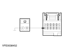
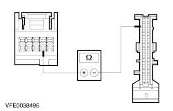
| B3: CHECK THE LEFT-HAND TURN SIGNAL LAMP CONTROL CIRCUIT FOR OPEN CIRCUIT |
| | 1 Ignition switch in position 0. |
| | 2 Disconnect CJB from connector C103. |
| | 3 Measure the resistance between the CJB, connector C103, pin 32, circuit 91S-LG1 (BK/YE), wiring harness side and the steering column multifunction switch, connector C459, pin 6, circuit 91S-LG1 (BK/YE), wiring harness side. |
| | Is a resistance of less than 2 Ohms registered? Yes CHECK and if necessary RENEW the CJB. CHECK the operation of the system. No LOCATE and REPAIR the open circuit between the CJB and the steering column multifunction switch, using the Wiring Diagrams. CHECK the operation of the system. |
| B4: CHECK THE GROUND CONNECTION OF THE LEFT-HAND TURN SIGNAL LAMPS |
| | 1 Ignition switch in position II. |
| | 2 OPERATE the horn. |
| | Does the horn work? Yes No LOCATE and RECTIFY the break in circuit 31-DA3 (BK) between soldered connection S121 and ground G37 using the Wiring Diagrams. CHECK the operation of the system. |
| B5: CHECK VOLTAGE SUPPLY TO LEFT-HAND TURN SIGNAL LAMPS |
| | 1 Ignition switch in position 0. |
| | 2 Disconnect CJB from connector C96. |
| | 3 Disconnect left-hand headlamp from connector C836. |
| | 4 Measure the resistance between the CJB, connector C96, pin 37, circuit 49S-LG11(A) (BU/OG), wiring harness side and the left-hand headlamp, connector C836, pin 3, circuit 49S-LG11 (BU/OG), wiring harness side. |
| | Is a resistance of less than 2 Ohms registered? Yes No LOCATE and RECTIFY the break in the circuit between the CJB and soldered connection S125 using the Wiring Diagrams. CHECK the operation of the system. |
| B6: CHECK THE CIRCUITS OF THE LEFT-HAND TURN SIGNAL LAMPS FOR A SHORT TO GROUND |
| | 1 Ignition switch in position 0. |
| | 2 Disconnect left-hand turn signal side lamp from connector C753. |
| | 3 Measure the resistance between the left-hand headlamp, connector C836, pin 3, circuit 49S-LG11 (BU/OG), wiring harness side and ground. |
| | 4 Measure the resistance between the left-hand turn signal side lamp, connector C753, pin 2, circuit 49S-LG13 (BU/RD), wiring harness side and ground. |
| | Is a resistance of more than 10,000 ohms measured? Yes RENEW the CJB. CHECK the operation of the system. No LOCATE and REPAIR the short to ground in the affected circuit using the Wiring Diagrams. CHECK the operation of the system. |
| B7: CHECK THE GROUND CONNECTION OF THE LEFT-HAND REAR LAMP ASSEMBLY |
| | 1 Ignition switch in position 0. |
| | 2 Disconnect Left-hand rear lamp assembly from connector. - Vehicles without trailer socket: C476
- Vehicles with trailer socket: C2005
|
| | 3 Measure the resistance between the rear lamp assembly: - Vehicles without trailer socket: Connector C476, pin 3, circuit 31-LF23 (BK), wiring harness side and ground.
- Vehicles with trailer socket: Connector C2005, pin 3, circuit (GN), wiring harness side and ground.
|
| | Is a resistance of less than 2 Ohms registered? Yes No LOCATE and RECTIFY the break in the circuit between the left-hand rear lamp assembly and ground connection G77 using the Wiring Diagrams. CHECK the operation of the system. |
| B8: CHECK THE LEFT-HAND REAR LAMP ASSEMBLY |
| | 1 Ignition switch in position II. |
| | 2 SWITCH ON left-hand turn signal. |
| | 3 Measure the voltage between the rear lamp assembly: - Vehicles without trailer socket: Connector C476, pin 6, circuit 49S-LG12 (BU), wiring harness side and ground.
- Vehicles with trailer socket: Connector C2005, pin 6, circuit (GY/WH), wiring harness side and ground.
|
| | Does the meter display fluctuating battery voltage? Yes CHECK and if necessary RENEW the left-hand rear lamp assembly. CHECK the operation of the system. No - Vehicles without trailer socket: GO to B9. |
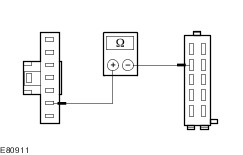
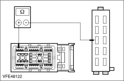
| B9: CHECK VOLTAGE SUPPLY TO LEFT-HAND REAR LAMP ASSEMBLY FOR OPEN CIRCUIT |
| | 1 Ignition switch in position 0. |
| | 2 Disconnect CJB from connector C100. |
| | 3 Measure the resistance between the CJB, connector C100, pin 32, circuit 49S-LG12 (BU), wiring harness side and the left-hand rear lamp assembly, connector C476, pin 6, circuit 49S-LG12 (BU), wiring harness side. |
| | Is a resistance of less than 2 Ohms registered? Yes No LOCATE and RECTIFY the break in the circuit between the CJB and the left-hand rear lamp assembly using the Wiring Diagrams. CHECK the operation of the system. |
| B10: CHECK THE CIRCUIT OF THE LEFT-HAND REAR LAMP ASSEMBLY FOR A SHORT TO GROUND |
| | 1 Measure the resistance between the left-hand rear lamp assembly, connector C476, pin 6, circuit 49S-LG12 (BU), wiring harness side and ground. |
| | Is a resistance of more than 10,000 Ohm measured? Yes CHECK and if necessary RENEW the CJB. CHECK the operation of the system. No LOCATE and RECTIFY the short to ground in the circuit between the CJB and the left-hand rear lamp assembly with the aid of the Wiring Diagrams. CHECK the operation of the system. |
| B11: CHECK THE VOLTAGE SUPPLY TO THE TRAILER CONTROL UNIT LEFT-HAND TURN SIGNAL |
| | 1 Ignition switch in position 0. |
| | 2 Disconnect trailer control unit from connector C2002. |
| | 3 Ignition switch in position II. |
| | 4 SWITCH ON left-hand turn signal. |
| | 5 Measure the voltage between the trailer control unit, connector C2002, pin 5, circuit (WH), wiring harness side and ground. |
| | Does the meter display fluctuating battery voltage? Yes No |
| B12: CHECK THE CIRCUIT BETWEEN THE CENTRAL JUNCTION BOX (CJB) AND THE TRAILER CONTROL UNIT FOR OPEN CIRCUIT |
| | 1 Ignition switch in position 0. |
| | 2 Disconnect CJB from connector C100. |
| | 3 Measure the resistance between the CJB, connector C100, pin 32, circuit 49S-LG12 (BU), wiring harness side and the trailer control unit, connector C2002, pin 5, circuit (WH), wiring harness side. |
| | Is a resistance of less than 2 Ohms registered? Yes No LOCATE and RECTIFY the break in the circuit between CJB and the trailer control unit using the Wiring Diagrams. CHECK the operation of the system. |
| B13: CHECK THE CIRCUIT BETWEEN THE CENTRAL JUNCTION BOX (CJB) AND THE TRAILER CONTROL UNIT FOR SHORT TO GROUND |
| | 1 Measure the resistance between the trailer control unit, connector C2002, pin 5, circuit (WH), wiring harness side and ground. |
| | Is a resistance of more than 10,000 ohms measured? Yes CHECK and if necessary RENEW the CJB. CHECK the operation of the system. No LOCATE and RECTIFY the short to ground in the circuit between the CJB and the trailer control unit with the aid of the Wiring Diagrams. CHECK the operation of the system. |
| B14: CHECK CIRCUIT (GY/WH) BETWEEN TRAILER CONTROL UNIT AND LEFT-HAND REAR LAMP ASSEMBLY FOR OPEN CIRCUIT |
| | 1 Disconnect left-hand rear lamp assembly from connector C2005. |
| | 2 Measure the resistance between the trailer control unit, connector C2002, pin 8, circuit (GY/WH), wiring harness side and the left-hand rear lamp assembly, connector C2005, pin 6, circuit (GY/WH), wiring harness side. |
| | Is a resistance of less than 2 Ohms registered? Yes No LOCATE and RECTIFY the break in the circuit between the trailer control unit and the left-hand rear lamp assembly using the Wiring Diagrams. CHECK the operation of the system. |
| B15: CHECK THE CIRCUIT (GY/WH) BETWEEN THE TRAILER CONTROL UNIT AND THE LEFT-HAND REAR LAMP ASSEMBLY FOR SHORT TO GROUND |
| | 1 Measure the resistance between the left-hand rear lamp assembly, connector C2005, pin 6, circuit (GY/WH), wiring harness side and ground. |
| | Is a resistance of more than 10,000 ohms measured? Yes CHECK and if necessary RENEW the trailer control unit. CHECK the operation of the system. No LOCATE and RECTIFY the short to ground in the circuit between the trailer control unit and the left-hand rear lamp assembly with the aid of the Wiring Diagrams. CHECK the operation of the system. |
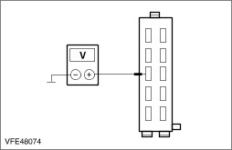
| B16: CHECK THE VOLTAGE SUPPLY TO THE LEFT-HAND FRONT TURN SIGNAL LAMP |
| | 1 Ignition switch in position 0. |
| | 2 Disconnect left-hand headlamp from connector C836. |
| | 3 Ignition switch in position II. |
| | 4 SWITCH ON left-hand turn signal. |
| | 5 Measure the voltage between the left-hand headlamp, connector C836, pin 3, circuit 49S-LG11 (BU/OG), wiring harness side and ground. |
| | Does the meter display fluctuating battery voltage? Yes LOCATE and REPAIR the break in circuit 31-LE31 (BK), between the headlamp and soldered connection S121, using the Wiring Diagrams. If necessary CHECK the headlamp and RENEW. CHECK the operation of the system. No LOCATE and RECTIFY the break in the circuit between soldered connection S125 and the headlamp using the Wiring Diagrams. CHECK the operation of the system. |
| B17: CHECK THE VOLTAGE SUPPLY OF THE LEFT-HAND TURN SIGNAL SIDE LAMP |
| | 1 Ignition switch in position 0. |
| | 2 Disconnect left-hand turn signal side lamp from connector C753. |
| | 3 Ignition switch in position II. |
| | 4 SWITCH ON left-hand turn signal. |
| | 5 Measure the voltage between the left-hand turn signal side lamp, connector C753, pin 2, circuit 49S-LG13 (BU/RD), wiring harness side and ground. |
| | Does the meter display fluctuating battery voltage? Yes LOCATE and RECTIFY the break in circuit 31-LG13 (BK) between the turn signal side lamp and soldered connection S121, using the Wiring Diagrams. CHECK and INSTALL A NEW turn signal side lamp if necessary. CHECK the operation of the system. No LOCATE and RECTIFY the break in the circuit between soldered connection S125 and the turn signal side lamp, using the Wiring Diagrams. CHECK the operation of the system. |
| B18: CHECK FUSE F55 (20 A) (CJB). |
| | 1 Ignition switch in position 0. |
| | 2 Disconnect fuse F55 (20 A) (CJB). |
| | 3 CHECK fuse F55 (20 A) (CJB). |
| | Is the fuse OK? Yes No RENEW fuse F55 (20 A) (CJB) and CHECK the operation of the system. If the fuse blows again, LOCATE and RECTIFY the short to ground using the Wiring Diagrams. CHECK the operation of the system. |
| B19: CHECK THE VOLTAGE SUPPLY TO FUSE F55 (20 A) (CJB) |
| | 1 Connect fuse F55 (20 A) (CJB). |
| | 2 Ignition switch in position II. |
| | 3 Measure the voltage between fuse F55 (20 A) (CJB) and ground. |
| | Is battery voltage measured? Yes No REPAIR the voltage supply to fuse F55 (20A) (CJB) using the Wiring Diagrams, CHECK the CJB and RENEW if necessary. CHECK the operation of the system. |
| B20: CHECK THE VOLTAGE SUPPLY TO THE DRIVER'S DOOR MULTIFUNCTION MODULE |
| | 1 Ignition switch in position 0. |
| | 2 Disconnect driver's door multifunction module from connector C729 . |
| | 3 Ignition switch in position II. |
| | 4 Measure the voltage between the driver's door multifunction module, connector C729, pin 9, circuit 29-AJ26 (OG/YE), wiring harness side and ground. |
| | Is battery voltage measured? Yes No LOCATE and RECTIFY the break in the circuit between the fuse and the driver's door multifunction module using the Wiring Diagrams. CHECK the operation of the system. |
| B21: CHECK THE GROUND CONNECTION OF THE DRIVER'S DOOR MULTIFUNCTION MODULE |
| | 1 Ignition switch in position 0. |
| | 2 Measure the resistance between the driver's door multifunction module, connector C729, pin 18, circuit 31-DA11A (BK), wiring harness side and ground. |
| | Is a resistance of less than 2 Ohms registered? Yes No LOCATE and RECTIFY the break in the circuit between the driver's door multifunction module and ground connection G12 (LHD) or G53 (RHD) using the Wiring Diagrams. CHECK the operation of the system. |
| B22: CHECK VOLTAGE SUPPLY OF ADDITIONAL TURN SIGNAL LAMP FOR OPEN CIRCUIT |
| | 1 Ignition switch in position 0. |
| | 2 Disconnect additional turn signal lamp from connector C807. |
| | 3 Disconnect driver's door multifunction module from connector C728. |
| | 4 Vehicles built up to 10/2004: |
| | 5 Measure the resistance between the driver's door multifunction module, connector C728, pin 7, circuit 49S-LG13 (BU/RD), wiring harness side and additional turn signal lamp, connector C807, pin 7, circuit 49S-LG13 (BU/RD), wiring harness side. |
| | 6 Vehicles built from 10/2004: |
| | 7 Measure the resistance between the driver's door multifunction module, connector C728, pin 7, circuit 49S-LG13 (BU/RD), wiring harness side and the additional turn signal lamp, connector C807, pin 7, circuit 49S-LG13 (BU/RD), wiring harness side. |
| | Is a resistance of less than 2 Ohms registered? Yes No LOCATE and RECTIFY the break in the circuit between the driver's door multifunction module and the additional turn signal lamp using the Wiring Diagrams. CHECK the operation of the system. |
| B23: CHECK THE GROUND CONNECTION OF THE ADDITIONAL TURN SIGNAL LAMP FOR OPEN CIRCUIT |
| | 1 Vehicles built up to 10/2004: |
| | 2 Measure the resistance between the driver's door multifunction module, connector C728, pin 3, circuit 31-HB35B (BK), wiring harness side, and the additional turn signal lamp, connector C807, pin 5, circuit 31-HB35B (BK), wiring harness side. |
| | 3 Vehicles built from 10/2004: |
| | 4 Measure the resistance between the driver's door multifunction module, connector C728, pin 3, circuit 31-HB35B (BK), wiring harness side, and the additional turn signal lamp, connector C807, pin 5, circuit 31-HB35B (BK), wiring harness side. |
| | Is a resistance of less than 2 Ohms registered? Yes CHECK and if necessary RENEW the additional turn signal lamp. CHECK the operation of the system. If the concern persists:
REFER to: Communications Network (418-00 Module Communications Network, Diagnosis and Testing).
No LOCATE and RECTIFY the break in the circuit between the driver's door multifunction module and the additional turn signal lamp using the Wiring Diagrams. CHECK the operation of the system. |
| B24: CHECK THE STEERING COLUMN MULTIFUNCTION SWITCH |
| | 1 Ignition switch in position 0. |
| | 2 Disconnect Steering column multifunction switch from connector C459. |
| | 3 Using a fused jumper wire (10 A) at the steering column multifunction switch, connect between connector C459, pin 7, circuit 91S-LG2 (BK/BU) and pin 10, circuit 91-LG27 (BK/GN), wiring harness side. |
| | 4 Ignition switch in position II. |
| | 5 CHECK right-hand turn signal lamp operation. |
| | Do the right-hand turn signal lamps illuminate? Yes INSTALL a new steering column multifunction switch. CHECK the operation of the system. No |
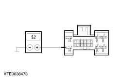
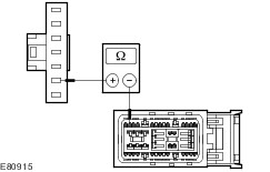
| B25: CHECK THE RIGHT-HAND TURN SIGNAL LAMP CONTROL CIRCUIT FOR OPEN CIRCUIT |
| | 1 Ignition switch in position 0. |
| | 2 Disconnect CJB from connector C103. |
| | 3 Measure the resistance between the CJB, connector C103, pin 31, circuit 91S-LG2 (BK/BU), wiring harness side and the steering column multifunction switch, connector C459, pin 7, circuit 91S-LG2 (BK/BU), wiring harness side and ground. |
| | Is a resistance of less than 2 Ohms registered? Yes RENEW the CJB. CHECK the operation of the system. No LOCATE and REPAIR the open circuit between the CJB and the steering column multifunction switch, using the Wiring Diagrams. CHECK the operation of the system. |
| B26: CHECK THE COMMON GROUND CONNECTION OF THE RIGHT-HAND TURN SIGNAL LAMPS |
| | 1 Ignition switch in position II. |
| | 2 SWITCH ON windshield wipers. |
| | Do the wipers operate? Yes No LOCATE and RECTIFY the break in circuit 31-DA4 (BK) between soldered connection S109 and ground G56 using the Wiring Diagrams. CHECK the operation of the system. |
| B27: CHECK VOLTAGE SUPPLY TO RIGHT-HAND SIGNAL LAMPS |
| | 1 Ignition switch in position 0. |
| | 2 Disconnect CJB from connector C96. |
| | 3 Disconnect right-hand headlamp from connector C837. |
| | 4 Measure the resistance between the CJB, connector C96, pin 36, circuit 49S-LG18A (BU), wiring harness side and the right-hand headlamp, connector C837, pin 3, circuit 49S-LG18 (BU), wiring harness side. |
| | Is a resistance of less than 2 Ohms registered? Yes No LOCATE and RECTIFY the break in the circuit between the CJB and soldered connection S126 using the Wiring Diagrams. CHECK the operation of the system. |
| B28: CHECK THE CIRCUITS OF THE LEFT-HAND TURN SIGNAL LAMPS FOR A SHORT TO GROUND |
| | 1 Disconnect right-hand turn signal side lamp from connector C754. |
| | 2 Measure the resistance between the right-hand headlamp, connector C837, pin 3, circuit 49S-LG18 (BU), wiring harness side and ground. |
| | 3 Measure the resistance between the right-hand turn signal side lamp, connector C754, pin 2, circuit 49S-LG20 (BU/WH), wiring harness side and ground. |
| | Is a resistance of more than 10,000 ohms measured? Yes RENEW the CJB. CHECK the operation of the system. No LOCATE and REPAIR the short to ground in the affected circuit using the Wiring Diagrams. CHECK the operation of the system. |
| B29: CHECK THE GROUND CONNECTION TO THE RIGHT-HAND REAR LAMP ASSEMBLY |
| | 1 Ignition switch in position 0. |
| | 2 Disconnect right-hand rear lamp assembly from connector:. - Vehicles without trailer socket: C477
- Vehicles with trailer socket: C2007
|
| | 3 Measure the resistance between the rear lamp assembly: - Vehicles without trailer socket: Connector C477, pin 3, circuit 31-LF24 (BK), wiring harness side and ground.
- Vehicles with trailer socket: Connector C2007, pin 3, circuit (GN), wiring harness side and ground.
|
| | Is a resistance of less than 2 Ohms registered? Yes No LOCATE and RECTIFY the break in the circuits between the right-hand rear lamp assembly and soldered connection S199 using the Wiring Diagrams. CHECK the operation of the system. |
| B30: CHECK THE RIGHT-HAND REAR LAMP ASSEMBLY |
| | 1 Ignition switch in position II. |
| | 2 SWITCH ON right-hand turn signal. |
| | 3 Measure the voltage between the rear lamp assembly - Vehicles without trailer socket: Connector C477, pin 6, circuit 49S-LG19 (BU/RD), wiring harness side and ground.
- Vehicles with trailer socket: Connector C2007, pin 6, circuit (GN/YE), wiring harness side and ground.
|
| | Does the meter display fluctuating battery voltage? Yes CHECK and if necessary RENEW the right-hand rear lamp assembly. CHECK the operation of the system. No - Vehicles without trailer socket: GO to B31. |
| B31: CHECK VOLTAGE SUPPLY TO RIGHT-HAND REAR LAMP ASSEMBLY FOR OPEN CIRCUIT |
| | 1 Ignition switch in position 0. |
| | 2 Disconnect CJB from connector C100. |
| | 3 Measure the resistance between the CJB, connector C100, pin 33, circuit 49S-LG19 (BU/RD), wiring harness side and the right-hand rear lamp assembly, connector C477, pin 6, circuit 49S-LG19 (BU/RD), wiring harness side. |
| | Is a resistance of less than 2 Ohms registered? Yes No LOCATE and RECTIFY the break in the circuit between the CJB and the right-hand rear lamp assembly using the Wiring Diagrams. CHECK the operation of the system. |
| B32: CHECK THE CIRCUIT OF THE RIGHT-HAND REAR LAMP ASSEMBLY FOR A SHORT TO GROUND |
| | 1 Ignition switch in position 0. |
| | 2 Measure the resistance between the right-hand rear lamp assembly, connector C477, pin 6, circuit 49S-LG19 (BU/RD), wiring harness side and ground. |
| | Is a resistance of more than 10,000 Ohm measured? Yes CHECK and if necessary RENEW the CJB. CHECK the operation of the system. No LOCATE and RECTIFY the short to ground in the circuit between the CJB and the right-hand rear lamp assembly with the aid of the Wiring Diagrams. CHECK the operation of the system. |
| B33: CHECK THE VOLTAGE SUPPLY TO THE TRAILER CONTROL UNIT RIGHT-HAND TURN SIGNAL |
| | 1 Ignition switch in position 0. |
| | 2 Disconnect trailer control unit from connector C2002. |
| | 3 Ignition switch in position II. |
| | 4 SWITCH ON right-hand turn signal. |
| | 5 Measure the voltage between the trailer control unit, connector C2002, pin 6, circuit (GN/RD), wiring harness side and ground. |
| | Does the meter display fluctuating battery voltage? Yes No |
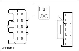
| B34: CHECK CIRCUIT 49S-LG19(BU/RD)/(GN/RD) BETWEEN THE CENTRAL JUNCTION BOX (CJB) AND THE TRAILER CONTROL UNIT FOR OPEN CIRCUIT |
| | 1 Ignition switch in position 0. |
| | 2 Disconnect CJB from connector C100. |
| | 3 Measure the resistance between the CJB, connector C100, pin 33, circuit 49S-LG19 (BU/RD), wiring harness side and the trailer control unit, connector C2002, pin 6, circuit (GN/RD), wiring harness side. |
| | Is a resistance of less than 2 Ohms registered? Yes No LOCATE and RECTIFY the break in the circuit between the CJB and the trailer control unit using the Wiring Diagrams. CHECK the operation of the system. |
| B35: CHECK THE CIRCUIT BETWEEN THE CENTRAL JUNCTION BOX (CJB) AND THE TRAILER CONTROL UNIT FOR SHORT TO GROUND |
| | 1 Measure the resistance between the trailer control unit, connector C2002, pin 6, circuit (GN/RD), wiring harness side and ground. |
| | Is a resistance of more than 10,000 ohms measured? Yes CHECK and if necessary RENEW the CJB. CHECK the operation of the system. No LOCATE and RECTIFY the short to ground in the circuit between the CJB and the trailer control unit with the aid of the Wiring Diagrams. CHECK the operation of the system. |
| B36: CHECK CIRCUIT (GN/YE) BETWEEN TRAILER CONTROL UNIT AND RIGHT-HAND REAR LAMP ASSEMBLY FOR OPEN CIRCUIT |
| | 1 Disconnect right-hand rear lamp assembly from connector C2007. |
| | 2 Measure the resistance between the trailer control unit, connector C2002, pin 10, circuit (GN/YE), wiring harness side and the right-hand rear lamp assembly, connector C2007, pin 6, circuit (GN/YE), wiring harness side. |
| | Is a resistance of less than 2 Ohms registered? Yes No LOCATE and RECTIFY the break in the circuit between the trailer control unit and the right-hand rear lamp assembly using the Wiring Diagrams. CHECK the operation of the system. |
| B37: CHECK THE CIRCUIT BETWEEN THE TRAILER CONTROL UNIT AND THE RIGHT-HAND REAR LAMP ASSEMBLY FOR A SHORT TO GROUND |
| | 1 Measure the resistance between the right-hand rear lamp assembly, connector C2007, pin 6, circuit (GN/YE), wiring harness side and ground. |
| | Is a resistance of more than 10,000 ohms measured? Yes CHECK and if necessary RENEW the trailer control unit. CHECK the operation of the system. No LOCATE and RECTIFY the short to ground in the circuit between the trailer control unit and the right-hand rear lamp assembly with the aid of the Wiring Diagrams. CHECK the operation of the system. |
| B38: CHECK THE VOLTAGE SUPPLY TO THE RIGHT-HAND FRONT TURN SIGNAL LAMP |
| | 1 Ignition switch in position 0. |
| | 2 Disconnect right-hand headlamp from connector C837. |
| | 3 Ignition switch in position II. |
| | 4 SWITCH ON right-hand turn signal. |
| | 5 Measure the voltage between the right-hand headlamp, connector C837, pin 3, circuit 49S-LG18 (BU), wiring harness side and ground. |
| | Does the meter display fluctuating battery voltage? Yes LOCATE and REPAIR the break in circuit 31-LE30 (BK), between the headlamp and soldered connection S109, using the Wiring Diagrams. If necessary CHECK the headlamp and RENEW. CHECK the operation of the system. No LOCATE and RECTIFY the break in the circuit between soldered connection S126 and the headlamp using the Wiring Diagrams. CHECK the operation of the system. |
| B39: CHECK THE VOLTAGE SUPPLY OF THE RIGHT-HAND TURN SIGNAL SIDE LAMP |
| | 1 Ignition switch in position 0. |
| | 2 Disconnect right-hand turn signal side lamp from connector C754. |
| | 3 Ignition switch in position II. |
| | 4 SWITCH ON right-hand turn signal. |
| | 5 Measure the voltage between the right-hand turn signal side lamp, connector C754, pin 2, circuit 49S-LG20 (BU/WH), wiring harness side and ground. |
| | Does the meter display fluctuating battery voltage? Yes LOCATE and RECTIFY the break in circuit 31-LG20 (BK) between the turn signal side lamp and soldered connection S109 using the Wiring Diagrams. CHECK and INSTALL A NEW turn signal side lamp if necessary. CHECK the operation of the system. No LOCATE and RECTIFY the break in the circuit between soldered connection S126 and the turn signal side lamp, using the Wiring Diagrams. CHECK the operation of the system. |
| B40: CHECK FUSE F41 (20 A) (CJB). |
| | 1 Ignition switch in position 0. |
| | 2 Disconnect fuse F41 (20 A) (CJB). |
| | 3 CHECK fuse F41 (20 A) (CJB). |
| | Is the fuse OK? Yes No RENEW fuse F41 (20 A) (CJB) and CHECK the operation of the system. If the fuse blows again, LOCATE and RECTIFY the short to ground using the Wiring Diagrams. CHECK the operation of the system. |
| B41: CHECK THE VOLTAGE SUPPLY TO FUSE F41 (20 A) (CJB) |
| | 1 Connect fuse F41 (20 A) (CJB). |
| | 2 Ignition switch in position II. |
| | 3 Measure the voltage between fuse F41 (20 A) (CJB) and ground. |
| | Is battery voltage measured? Yes No REPAIR the voltage supply to fuse F41 (20A) (CJB) using the Wiring Diagrams, CHECK the CJB and RENEW if necessary. CHECK the operation of the system. |
| B42: CHECK THE VOLTAGE SUPPLY TO THE PASSENGER'S DOOR MULTIFUNCTION MODULE |
| | 1 Ignition switch in position 0. |
| | 2 Disconnect passenger's door multifunction module from connector C722. |
| | 3 Ignition switch in position II. |
| | 4 Measure the voltage between the passenger's door multifunction module, connector C722, pin 9, circuit 29-AJ27 (OG/WH), wiring harness side and ground. |
| | Is battery voltage measured? Yes No LOCATE and RECTIFY the break in the circuit between the fuse and the passenger's door multifunction module using the Wiring Diagrams. CHECK the operation of the system. |
| B43: CHECK THE GROUND CONNECTION TO THE PASSENGER'S DOOR MULTIFUNCTION MODULE |
| | 1 Ignition switch in position 0. |
| | 2 Measure the resistance between the passenger's door multifunction module, connector C722, pin 18, circuit 31-DA12A (BK), wiring harness side and ground. |
| | Is a resistance of less than 2 Ohms registered? Yes No LOCATE and RECTIFY the break in the circuit between the passenger's door multifunction module and ground connection G53 (LHD) or G12 (RHD) using the Wiring Diagrams. CHECK the operation of the system. |
| B44: CHECK VOLTAGE SUPPLY OF ADDITIONAL TURN SIGNAL LAMP FOR OPEN CIRCUIT |
| | 1 Ignition switch in position 0. |
| | 2 Disconnect additional turn signal lamp from connector C821. |
| | 3 Disconnect passenger's door multifunction module from connector C723. |
| | 4 Vehicles built up to 10/2004: |
| | 5 Measure the resistance between the passenger's door multifunction module, connector C723, pin 7, circuit 49S-LG20 (BU/WH), wiring harness side and the additional turn signal lamp, connector C821, pin 7, circuit 49S-LG20 (BU/WH), wiring harness side. |
| | 6 Vehicles built from 10/2004: |
| | 7 Measure the resistance between the passenger's door multifunction module, connector C723, pin 7, circuit 49S-LG20 (BU/WH), wiring harness side and the additional turn signal lamp, connector C821, pin 7, circuit 49S-LG20 (BU/WH), wiring harness side. |
| | Is a resistance of less than 2 Ohms registered? Yes No LOCATE and RECTIFY the break in the circuit between the passenger's door multifunction module and the additional turn signal lamp using the Wiring Diagrams. CHECK the operation of the system. |
| B45: CHECK THE GROUND CONNECTION OF THE ADDITIONAL TURN SIGNAL LAMP FOR OPEN CIRCUIT |
| | 1 Vehicles built up to 10/2004: |
| | 2 Measure the resistance between the passenger's door multifunction module, connector C723, pin 3, circuit 31-HB36B (BK), wiring harness side, and the additional turn signal lamp, connector C821, pin 5, circuit 31-HB36B (BK), wiring harness side. |
| | 3 Vehicles built from 10/2004: |
| | 4 Measure the resistance between the passenger's door multifunction module, connector C723, pin 3, circuit 31-HB36B (BK), wiring harness side, and the additional turn signal lamp, connector C821, pin 5, circuit 31-HB36B (BK), wiring harness side. |
| | Is a resistance of less than 2 Ohms registered? Yes CHECK and if necessary RENEW the additional turn signal lamp. CHECK the operation of the system. If the concern persists:
REFER to: Communications Network (418-00 Module Communications Network, Diagnosis and Testing).
No LOCATE and RECTIFY the break in the circuit between the passenger's door multifunction module and the additional turn signal lamp using the Wiring Diagrams. CHECK the operation of the system. |