| Removal and Installation Special Tool(s) | | Remover/Installer, coolant hose clamp 303-397 | General Equipment Hose clamp - coolant hose Vehicles with fuel powered additional heater | | -
Drain the cooling system. For additional information, refer to: Cooling System Draining, Filling and Bleeding (303-03A Engine Cooling - 1.6L Duratec-16V (Sigma), General Procedures), Cooling System Draining, Filling and Bleeding (303-03B Engine Cooling - 1.6L Duratec-16V Ti-VCT (Sigma), General Procedures), Cooling System Draining, Filling and Bleeding (303-03C Engine Cooling - 1.8L Duratec-HE (MI4)/2.0L Duratec-HE (MI4), General Procedures), Cooling System Draining, Filling and Bleeding (303-03F Engine Cooling - 1.8L Duratorq-TDCi (Lynx) Diesel, General Procedures). | | | -
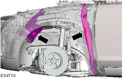
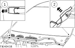
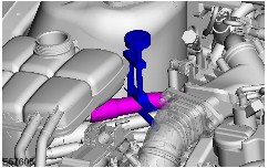
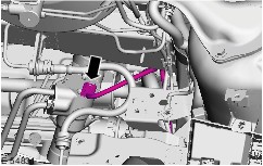
NOTE:Mark installation position of front engine mounting bracket with respect to the wheelhouse. Remove the front engine mounting bracket bolts. - Pull the engine forwards.
| All vehicles | | -
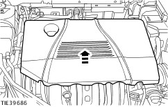
Remove the engine cover (1.8L shown). - Remove the oil filler cap.
| | | -
Remove the left and right front wheels.
For additional information, refer to: Wheel and Tire (204-04 Wheels and Tires, Removal and Installation).
| | | -
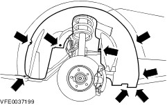
Remove the left and right front wheel arch covers. | | | -
Remove the splash shields. | | | -
Remove the front bumper cover.
For additional information, refer to: Front Bumper Cover - Vehicles Built Up To: 03/2007 (501-19 Bumpers, Removal and Installation).
| | | -
Empty the windshield washer reservoir. | | | -
Remove the front scuff plate - passenger side.
For additional information, refer to: Front Scuff Plate Trim Panel (501-05 Interior Trim and Ornamentation, Removal and Installation).
| | | -
Remove the centre console extension. For additional information, refer to: (501-12 Instrument Panel and Console) Floor Console Extension (Removal and Installation), Floor Console Extension - Vehicles Built From: 03/2007, Vehicles With: Center Armrest (Removal and Installation). | | | -
Remove the left and right turn signal lamps. - Pull turn signal lamps out of wing, turn bulb housing and pull out.
| Vehicles without anti-lock brake system | | -
CAUTION:If brake fluid comes into contact with the paintwork, the affected area must be washed down immediately with cold water. Detach the brake fluid reservoir from the water trap and secure it to one side. | | | -
Remove the windshield wiper arm cover (if installed). | | | -
CAUTION:Make sure that the windshield wiper motor is in the park position. Remove the windshield wiper arms. | | | -
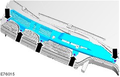
Remove the cowl grille. - Detach the cowl grille clips.
- Detach the cowl grille from the windshield glass lower weatherstrip and remove.
| | | -
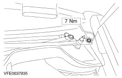
Remove the windshield wiper linkage bolt. | | | -
Remove the bulkhead extension. - Pull the bulkhead extension out of the clips.
| | | -
Remove the battery tray. For additional information, refer to: (414-01 Battery, Mounting and Cables) Battery Tray - 1.6L Duratec-16V (Sigma)/1.8L Duratec-HE (MI4)/2.0L Duratec-HE (MI4) (Removal and Installation), Battery Tray - 1.6L Duratorq-TDCi (DV) Diesel/1.8L Duratorq-TDCi (Lynx) Diesel/2.0L Duratorq-TDCi (DW) Diesel (Removal and Installation). | Vehicles with anti-lock brake system | | -
Remove the hydraulic control unit (HCU). For additional information, refer to: Hydraulische Regeleinheit (HCU) (206-09 Antiblockierbremssystem, Removal and Installation), Hydraulic Control Unit (HCU) (206-09C Anti-Lock Control - Stability Assist, Removal and Installation). | Vehicles with manual transaxle | | -
CAUTION:If brake fluid comes into contact with the paintwork, the affected area must be washed down immediately with cold water. CAUTION:Close off lines to prevent loss of brake fluid and dirt from entering. Detach the supply hose of the clutch master cylinder and the supply line of the clutch slave cylinder from the clutch master cylinder. - Release the clutch master cylinder supply hose clip.
- Release the clutch slave cylinder supply line clip.
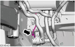
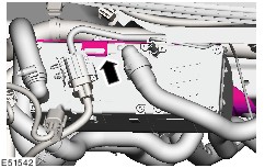
| 21. Remove the components in the order indicated in the following illustration(s) and table(s). 1 - Right-hand and left-hand connectors - heated windshield 2 - Connector - heated washer jets (if fitted) 3 - Clips - engine compartment wiring harness NOTE:Only vehicles with anti-theft alarm horn with integral battery 5 - Nut - anti-theft alarm system horn 6 - Anti-theft alarm system horn 7 - Connector - anti-theft alarm system horn CAUTION:Close off the coolant hoses, fuel hose and fuel powered additional heater to stop dirt from entering. NOTE:Only vehicles with fuel powered additional heater 9 - Exhaust pipe - fuel powered additional heater 11 - Right-hand coolant hose - fuel powered additional heater 12 - Fuel hose - fuel powered additional heater 13 - Left-hand coolant hose - fuel powered additional heater 14 - Bolt - fuel powered additional heater NOTE:Only vehicles with fuel powered additional heater 16 - Nuts - fuel powered additional heater bracket 17 - Bracket - fuel powered additional heater (secure to one side) 19 - Windshield washer upper reservoir upper retaining bolt 20 - Windshield washer pump connector 22 - Clips - engine compartment wiring harness 23 - Connector - anti-lock brake system wheel sensor 24 - Connector - headlamp range control front sensor (if fitted) 27 - Clips - engine compartment wiring harness 28 - Connector - anti-lock brake system wheel sensor 33 - Low pressure switch connector 34 - High pressure switch connector 35 - Bracket - evaporator refrigerant lines (unclip) 36 - Clips - engine compartment wiring harness 38 - Connector - brake fluid level warning light switch 39 - Battery junction box (BJB) cover 41 - Engine wiring harness connector 44 - Connector - power steering pump (if fitted) 46 - Ambient Air Temperature (AAT) connector 47 - Connector - pre-glow relay (if fitted) 48 - Clips - engine compartment wiring harness 50 - Connector - bonnet lock 51 - Connector - anti-theft alarm system sensor 52 - Connector - cooling fan 53 - Connector - park position sensor 54 - Clips - engine compartment wiring harness 55 - Footwell trim panel screws 57 - Glove compartment screws 58 - Glove compartment light switch connector 59 - Glove compartment light connector 65 - Clips - engine compartment wiring harness 66 - Connector - electric booster heater (if fitted) 22. To install, reverse the removal procedure. CAUTION:Ensure that the front engine mounting bracket is in the original installation position. CAUTION:Move the windshield wiper motor to the parked position before installing the wiper arms. | | -
Bleed the clutch system.
For additional information, refer to: Clutch System Bleeding (308-00 Manual Transmission/Transaxle and Clutch - General Information, General Procedures).
| Removal Details Item 4 : Engine compartment wiring harness | | -
Slide the wiring harness into the wheelhouse. | Item 8 : Intake hose - fuel powered additional heater | | -
Raise and support the vehicle.
For additional information, refer to: Lifting (100-02 Jacking and Lifting, Description and Operation).
| | | -
Disconnect the additional coolant pump electrical connector (if fitted). | Item 10 : Connector - fuel powered additional heater Item 15 : Fuel powered additional heater | | -
Unclip the fuel powered additional heater from the bracket. | Item 18 : Windshield washer upper reservoir lower retaining bolt | | -
Remove the reservoir filler neck. - Remove the screws.
- Pull out the filler neck.
| | | -
Raise and support the vehicle.
For additional information, refer to: Lifting (100-02 Jacking and Lifting, Description and Operation).
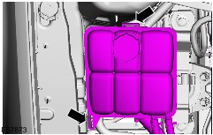
| Item 21 : Windshield washer upper reservoir (secure to one side) | | -
Pull the connecting piece of the lower reservoir from the upper reservoir. | Item 26 : Engine compartment wiring harness | | -
Slide the wiring harness into the engine compartment. | Item 30 : Engine compartment wiring harness | | -
Slide the wiring harness into the engine compartment. | Item 31 : Coolant hose, coolant expansion tank (only 1.6L diesel engine) | | -
Empty the coolant expansion tank. | | | -
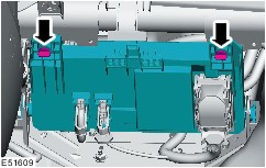
CAUTION:Clamp shut the coolant hose of the expansion tank using the hose clamp, to prevent coolant escaping from the hose. Clamp the coolant hose shut. | Item 32 : Coolant expansion tank | | -
Unclip the coolant expansion tank and place to one side. | Item 37 : Engine compartment wiring harness | | -
Pull out the wiring harness under the refrigerant lines. | Item 49 : Engine compartment wiring harness | | -
Slide the wiring harness into the engine compartment. | Item 60 : Glove compartment | | -
Disconnect the passenger air bag deactivation (PAD) switch electrical connector (if equipped). | Item 61 : Lower connector - dashboard wiring harness | | -
Detach the connector housing from the A-pillar. | Item 62 : Upper connector - dashboard wiring harness | | -
Cut open the bulkhead insulation matting and push to one side. | | | -
Detach the connector housing from the bulkhead. | Item 63 : Connector - engine compartment wiring harness | | -
Detach the central junction box (CJB) from the reinforcing element. | | | -
Detach the CJB from the CJB bracket. - Turn the CJB downwards.
- Pull out the CJB.
| | | -
Detach the wiring harness from the CJB bracket (if fitted). | | | -
Disconnect the engine wiring harness connector from the CJB. | Item 64 : Ground cable bolts | | -
Unclip the wiring harness at the bulkhead. | Item 67 : Engine compartment wiring harness | | -
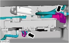
Slide the engine compartment wiring harness, together with the rubber grommet, into the engine compartment. | Item 68 : Engine compartment wiring harness (LHD version shown) | | -
NOTE:Only vehicles with electrohydraulic power steering Disconnect the steer angle sensor electrical connector (if fitted). | | | -
Unclip the supply line of the clutch slave cylinder from the bracket. | | | -
Unclip the brake pipe and remove the clip. | | | -
Pull out the wiring harness under the refrigerant lines and the coolant lines. | |