| Removal and Installation Special Tool(s) | | Alignment Pins, Subframe 205-316 (15-097A) | | | Separator, Ball Joint 211-020 (13-006) | | | Expander, Teflon Seal 211-188 (13-015) | Removal All Vehicles | | -
Disconnect the battery ground cable. | | | -
Center the steering wheel. - Lock in position, remove the ignition key.
| | | -
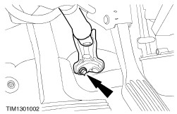
Disconnect the steering column shaft from the flexible coupling. - Rotate the clamp plate to disengage.
| | | -
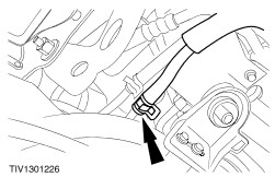
CAUTION:When removing the floor seal do not damage the sealing clips. Remove the floor seal from the bulkhead. - Release the retaining clips.
- Disconnect the upper retaining clip.
- Remove the floor seal.
| | | -
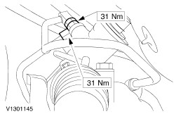
Remove the steering column shaft flexible coupling. | | | -
Remove the radiator splash shield. | | | -
Disconnect the fluid cooler line. - Allow the fluid to drain into a suitable container.
| | | -
Remove the two fender splash shields. | Vehicles built up to 08/2000 | | -
Detach the bumper support brackets from the front subframe. | Vehicles built 08/2000 onwards | | -
Detach the bumper support brackets from the front subframe. | Vehicles with 2.5L engine | | -
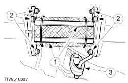
CAUTION:Over bending of the flexible pipe may cause damage resulting in failure. Remove the exhaust flexible pipe. - Support the flexible pipe with a support wrap or suitable splint assembly.
- Remove and discard the gaskets and nuts.
- Detach the exhaust hanger insulator.
| Vehicles with automatic transaxle | | -
Detach the engine rear support insulator. | Vehicles with manual transaxle | | -
Remove the engine rear support insulator center bolt. | | | -
NOTE:Right-hand drive vehicles with 2.5L engine. Remove the engine rear support insulator bracket. | All Vehicles | | -
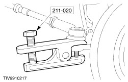
CAUTION:Leave the tie-rod end retaining nuts in place to protect the ball joint studs. Loosen the tie-rod end retaining nuts. | | | -
CAUTION:Protect the ball joint seals using a soft cloth to prevent damage. Using the special tool, detach the tie-rod ends from the wheel knuckles. - Remove and discard the retaining nuts
| | | -
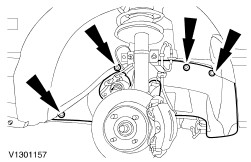
Lower the subframe to gain access to the steering gear tubes. - Loosen the subframe front bolts two complete turns.
- Remove the subframe rear bolts.
| Right-hand drive vehicles | | -
Detach the high-pressure tube support bracket. | Left-hand drive vehicles | | -
Detach the high-pressure tube support bracket. | All Vehicles | | -
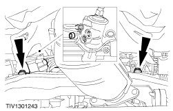
NOTE:Left-hand drive shown, right-hand drive similar. Detach the return tube support bracket. | | | -
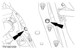
CAUTION:Whenever the steering gear unions are disconnected the steering gear valve body ports should be plugged to prevent dirt ingress. NOTE:Left-hand drive shown, right-hand drive similar. Disconnect the tube unions from the steering gear. - Disconnect the high-pressure tube union.
- Disconnect the return tube union.
- Allow the fluid to drain into a suitable container.
| Left-hand drive vehicles | | -
Remove the steering gear cover plate. | Right-hand drive vehicles | | -
Remove the steering gear cover plate. | All Vehicles | | -
CAUTION:Make sure that the pressure check valve does not fall out of the valve body pressure port when the steering gear is being removed. CAUTION:On right-hand drive vehicles make sure the valve body does not damage the generator wiring harness. NOTE:Left-hand drive shown, right-hand drive similar. Remove the steering gear. | Installation All Vehicles | | -
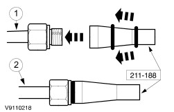
Using the special tool, install new union O-ring seals. - Push the new O-ring seal onto the special tool.
- Locate the tool over the union and ease the O-ring seal onto the union.
| | | -
CAUTION:Make sure the pressure check valve is correctly located. NOTE:Left-hand drive shown, right-hand drive similar. Install the steering gear. | Right-hand drive vehicles | | -
Install the steering gear cover plate. | Left-hand drive vehicles | | -
Install the steering gear cover plate. | All Vehicles | | -
NOTE:Left-hand drive shown, right-hand drive similar Connect the tube unions. | | | -
NOTE:Left-hand drive shown, right-hand drive similar. Install the return tube support bracket. | Right-hand drive vehicles | | -
Install the high-pressure tube support bracket. | Left-hand drive vehicles | | -
Install the high-pressure tube support bracket. | All Vehicles | | -
Using the special tool, align the subframe. - Install the alignment pins in the subframe aligning holes.
- Install the locking pins.
- Tighten the alignment pin sleeves.
| | | -
Install and secure the subframe bolts. | | | -
Remove the special tool (subframe alignment pins). | Vehicles with automatic transaxle | | -
Install the engine rear support insulator. | Vehicles with manual transaxle | | -
NOTE:Right-hand drive vehicles with 2.5L engine. Install the engine rear support insulator bracket. | | | -
Install the engine rear support insulator center bolt. | Vehicles with 2.5L engine | | -
CAUTION:Over bending of the flexible pipe may cause damage resulting in failure. NOTE:Install new gaskets and nuts. Install the exhaust flexible pipe. - After installation, remove the flexible pipe support.
| All Vehicles | | -
WARNING:Install new tie-rod end retaining nuts. Failure to follow this instruction, may result in personal injury. Attach the tie-rod ends to the wheel knuckles. | | | -
Install the two fender splash shields. | | | -
Connect the fluid cooler line. | | | -
Install the radiator splash shield. | Vehicles built up to 08/2000 | | -
Attach the bumper support brackets to the front subframe. | Vehicles built 08/2000 onwards | | -
Attach the bumper support brackets to the front subframe. | All Vehicles | | -
CAUTION:Before lowering the vehicle, make sure the steering is in the straight ahead position. Install the driver side front wheel and tire. For additional information, refer to Section 204-04 Wheels and Tires. | | | -
WARNING:Install a new pinch bolt. Failure to follow this instruction may result in personal injury. Install the steering column shaft flexible coupling. | | | -
WARNING:Install a new pinch bolt. Failure to follow this instruction may result in personal injury. Connect the steering column shaft to the flexible coupling. | | | -
Connect the battery ground cable. | | | -
Fill the power steering system. For additional information, refer to the procedure in this section: Start Up Procedure After Pump/Gear Overhaul. | |