| Disassembly and Assembly Electric drill Stud extractor Disassembly All Vehicles | | -
Remove the steering column. For additional information, refer to Steering column in this section. | | | -
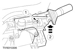
Remove the indicator/flash to pass switch. - Release the retaining tang.
- Remove the switch.
| | | -
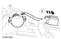
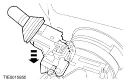
Remove the wiper/washer switch. - Release the retaining tang.
- Remove the switch.
| | | -
Detach the driver air bag module. | | | -
Remove the driver air bag module. - Disconnect the driver air bag module electrical connector.
| | | -
Disconnect the horn (and speed control if equipped) electrical connector. | | | -
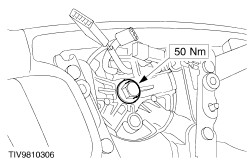
WARNING:Make sure the air bag module electrical connector is not damaged as the steering wheel is removed. Failure to follow this instruction may result in personal injury. Remove the steering wheel. | | | -
Remove the air bag sliding contact. - Release each of the three retaining tangs using a thin bladed screwdriver.
| Vehicles with 2.5L (200 PS) engine | | -
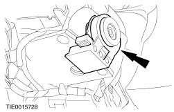
Remove the passive anti–theft system (PATS) tranceiver. | | | -
Using a suitable electric hand drill and stud extractor remove the lower steering lock shield bolts. | | | -
Remove the steering lock shield. | All vehicles | | -
Remove the (PATS) transceiver. | | | -
Remove the key interlock actuator (if equipped). | | | -
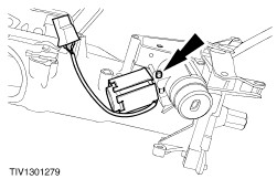
Remove the ignition switch. - Remove the ignition switch retaining screws.
- Detach the ignition switch electrical connector.
| | | -
Remove the ignition switch lock cylinder. - Insert and turn the key to accessory (position I).
- Depress the retainer.
- Remove the ignition lock cylinder.
| | | -
Remove the upper bearing cap. | Assembly All vehicles | | -
Install the upper bearing cap. | | | -
Install the ignition switch lock cylinder. - Insert and turn the key to accessory (position 1).
- Install the ignition switch lock cylinder.
| | | -
Install the ignition switch. - Install the ignition switch retaining screws.
- Attach the ignition switch electrical connector.
| | | -
Install the (PATS) transceiver. | Vehicles with 2.5L (200 PS) engine | | -
CAUTION:When installing the steering lock shield make sure that no cables are trapped or damaged. NOTE:The steering lock shield retaining bolts are designed to shear at the specified torque. NOTE:The steering lock shield retaining bolts must be hand started before tightening with a power tool. Install the steering lock shield. | | | -
Install the (PATS) transceiver. | All vehicles | | -
Install the air bag sliding contact. | | | -
WARNING:Make sure the air bag module electrical connector is not damaged as the steering wheel is installed. Failure to follow this instruction may result in personal injury. Install the steering wheel. | | | -
Connect the horn (and speed control if equipped) electrical connector. | | | -
Connect the driver air bag module. | | | -
Install the driver air bag module. | | | -
Install the wiper/washer switch. | | | -
Install the indicator/flash to pass switch. | | | -
Install the steering column. For additional information, refer to Steering Column in this section. | |