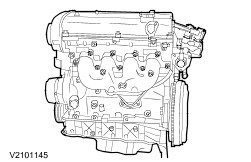
The Cougar is now equipped with the new 2,0L Zetec-E engine familiar from Mondeo.
Engine codes
The engine codes for the 2.0L Zetec-E engines are:
- 2,0L Zetec-E-Motor (D3) - EDBA
- 2,0L Zetec-E-Motor (E4) - EBBC
- 2,0L Zetec-E-Motor (Stage II) - EBBD
- 2,0L Zetec-E-Motor (Stage III) - EDBB
Construction of the Zetec-E engine
Basic concept
The Zetec-E engine is an in-line four cylinder engine with two overhead camshafts and 16 valves. The 16 valve cylinder head achieves a better cylinder charge particularly at high engine speeds.
The cylinder head is made of aluminum alloy and the cylinder block of cast iron.
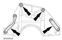
Timing belt center cover/front engine mounting bracket
The new timing belt cover has a vertical rib to increase its rigidity. This means that both the timing belt centre cover and the front engine mounting must be removed at the same time in order to change the timing belt.
Cylinder head
Combustion chamber
The centrally positioned spark plug in the roof shaped combustion chamber causes the mixture found in the combustion chamber to ignite. Positioning the spark plug centrally causes an even spread of the flame front through the combustion chamber and thus at the same time reduces the tendency of the engine to knock.
Valve gear
The two camshafts are driven by one common drive belt and operate four valves per cylinder through adjustable tappets. Because of the exhaust gas stream flowing past them, the exhaust valves are subjected to particularly high temperatures. The exhaust valves are specially coated so that they are better able to dissipate heat. Each valve is closed by its own single valve spring. Adjustment shims in the valve tappets are changed in order to adjust the valve clearance. These are available in 52 different thicknesses. The thickness of the adjusting shim is stamped on the back face as a numerical value accurate to a hundredth of a millimetre (example: the number 222 = 2,22 mm). Because of the limited space in the cylinder head the camshaft must be removed in order to change the adjusting shims. Absolute accuracy is therefore necessary during the adjustment procedure in order to avoid having to remove and install the camshaft more than once. The cams on the camshaft run off-centre on the valve tappets. Because of this, from an engine speed of about 3000 rev/min the tappets are caused to rotate, and they transmit this turning movement to the valves. Turning of the valves is desirable because this leads to an even seating of the valves on their seats and prevents the valves from bedding in at one position and leaking.
Valve gear
1
-
Bolt - camshaft bearing cap
5
-
Oil gallery blanking plug
6
-
Valve clearance adjusting shim
17
-
Engine lifting eye bolt
20
-
Camshaft timing belt pulleys.
22
-
Front camshaft bearing cap guide sleeve
23
-
Front camshaft bearing cap
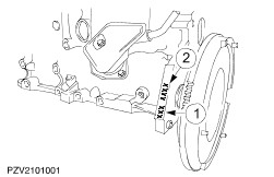
Timing belt tensioner
CAUTION:Only tension the timing belt tensioner anticlockwise.
Correct timing belt tension is ensured by the automatic timing belt tensioner. To do this it is set to its base position when a new timing belt is put in place (arrow point (3) and marking (2) line up). This base setting is taken over by a cam (4). A further cam which is under spring pressure ensures the correct timing belt tension during operation. The working range of the timing belt tensioner is 30° either side of the centre position.
NOTE:The timing belt must not be re-tensioned because there is a danger that the working range would be exceeded in one direction. The base setting of the timing belt tensioner is only valid for new timing belts. Re-tensioning can therefore lead to splitting or run-out of the timing belt.
After removing the adjusting tool and the alignment pin the base setting can no longer be checked (the force of the valve springs puts pressure on the timing belt and alters the position of the timing belt tensioner).
Automatic timing belt tensioner
Shims are to be installed at the lower crankcase in order to level out the gap between the transmission and the lower crankcase if it is too large (see Technical Data and Specifications).
Oil pan
The assembly is closed at the bottom by a pressed steel sump which is attached directly to the lower crankcase. Sealing is achieved using a 3 mm wide bead of sealer.
Engine management
EEC V Module
Engine management of the Zetec-E engines is handled by the EEC V module. To do this it requires a great deal of information about the current operating parameters of the engine and the automatic transmission (CD4E). The EEC V module obtains this information through sensors.
- The EEC V module controls:
-
the fully electronic ignition system (EI)
-
sequential fuel injection (SEFI),
-
the air conditioning system together with the cooling system and
-
transmission control of the CD4E automatic transmission (if equipped).