| In-vehicle Repair Special Tool(s) | | Remover, Vibration Damper, Crankshaft 303 - 338 (21153B) | | | Installer, Pulley, Camshaft 303 - 458 (21192) | Materials Name Specification Hypoidoil SQM - 2C9002 - AA Removal | | -
Remove the RH valve cover. For additional information, refer to Valve Cover-RH in this section. | | | -
Remove the LH valve cover. For additional information, refer to Valve Cover-LH in this section. | | | -
Remove the crankshaft pulley. For additional information, refer to Crankshaft Pulley in this section. | | | -
Install the crankshaft pulley bolt and washer. | | | -
CAUTION:Rotate the crankshaft clockwise to position the crankshaft keyway to the 11 o'clock position and the engine to top dead center (TDC) No. 1 cylinder prior to the removal and installation of the camshafts and the roller followers or damage to the engine may occur. CAUTION:Do not rotate the crankshaft counterclockwise. The timing chains may bind causing engine damage. NOTE:If the roller finger followers (RFF) marks do not align, rotate the crankshaft one complete revolution. Rotate the crankshaft keyway to position the No. 1 cylinder at top dead center (TDC). - Rotate the crankshaft keyway clockwise to the 11 o'clock position.
- The RFF marks on the back of the camshaft sprockets must line up with one another.
| | | -
NOTE:The RH camshafts are in the neutral position. Rotate the crankshaft clockwise to position the crankshaft keyway in the 3 o'clock position. | | | -
Rotate the belt tensioner clockwise towards the camshaft drive pulley to relieve the drive belt tension and remove the belt. | | | -
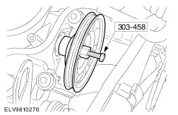
Remove the water pump drive pulley. - Install special tool.
- Install special tool then turn center bolt.
- Remove the water pump drive pulley.
| | | -
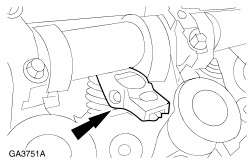
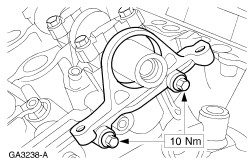
CAUTION:Protect the camshaft surface when removing the oil seal retainer. Remove the bolts and the camshaft oil seal retainer and discard the gasket. | | | -
CAUTION:Cylinder head and camshaft bearing caps are numbered to make sure they are assembled in their original position. When removed, keep the bearing caps with the cylinder head they were removed from. Do not mix the caps. NOTE:Do not loosen any of the other bolts until the thrust caps are removed. Remove the RH camshaft thrust caps 1R and 5R. - Remove the bolts.
- Remove the caps.
| | | -
NOTE:Loosen bolts on several passes. Do not remove bolts completely. NOTE:Camshaft bearing caps are dowelled to cylinder head. Use a plastic mallet to loosen caps if necessary. Loosen the remaining bolts 7 - 8 turns in the indicated sequence in several passes to allow the RH camshafts to be slowly raised. | | | -
NOTE:If the camshaft followers and lash adjusters are to be reused, mark their positions to make sure they are assembled in the original location. Remove the twelve RH camshaft roller finger followers. | | | -
CAUTION:Do not rotate the crankshaft counterclockwise. The timing chains may bind causing engine damage. Rotate the crankshaft clockwise two revolutions and position the crankshaft keyway in the 11 o'clock position. - The LH camshafts will be in the neutral position.
- Verify the RFF flags on the LH camshafts are aligned.
| | | -
CAUTION:Cylinder head and camshaft bearing caps are numbered to make sure they are assembled in their original position. When removed, keep the the bearing caps with the cylinder head they were removed from. Do not mix the caps. NOTE:Do not loosen any of the other bolts until the thrust caps are removed. Remove the LH camshaft thrust caps 1L and 5L. - Remove the bolts.
- Remove the caps.
| | | -
NOTE:Loosen bolts on several passes. Do not remove bolts completely. Loosen the remaining bolts seven to eight turns in the indicated sequence to allow the LH camshafts to be raised. | | | -
NOTE:If the camshaft followers and lash adjusters are to be reused, mark their positions to make sure they are assembled in the original position. Remove the twelve LH camshaft roller finger followers. | Installation | | -
CAUTION:The crankshaft keyway must be in the 11 o'clock position prior to installation of the roller finger followers. Failure to do so may lead to engine damage. NOTE:Verify the RFF flags on the camshaft sprockets are aligned. NOTE:Make sure the roller finger followers are installed in their original locations. Install the twelve LH camshaft roller finger followers. - Apply Hypoidoil and lubricate the roller finger followers before installation.
| | | -
CAUTION:Install the camshaft journal thrust caps last or damage to the thrust caps may occur. CAUTION:Use thrust caps 1L and 5L to align camshaft end play prior to tightening the other bearing caps. Position and tighten the LH cylinder head bearing caps in the indicated sequence in several passes. | | | -
CAUTION:Do not rotate the crankshaft counterclockwise. The timing chains may bind causing engine damage. NOTE:The RH camshafts are in the neutral position. Rotate the crankshaft clockwise to position the crankshaft keyway in the 3 o'clock position. | | | -
CAUTION:The crankshaft keyway must be in the 3 o'clock position prior to installation of the RH roller finger followers. Failure to do so may lead to engine damage. NOTE:Make sure the roller finger followers are installed in their original position. Install the twelve RH camshaft roller finger followers. - Apply Hypoidoil and lubricate the roller finger followers before installation.
| | | -
CAUTION:Install the camshaft bearing thrust caps last or damage to the thrust caps may occur. CAUTION:Use thrust caps 1R and 5R to align camshaft end play prior to tightening the other bearing caps. Install the camshaft bearing caps (RH cylinder head). - Tighten the bearing caps evenly according to the indicated sequence in several passes.
| | | -
NOTE:Install a new gasket when installing the camshaft oil seal retainer. Position the camshaft oil seal retainer on the locating dowels and install the bolts. | | | -
Using the special tool, install the water pump drive pulley. | | | -
Rotate the belt tensioner towards the camshaft drive pulley and install the drive belt. | | | -
Remove the crankshaft pulley bolt and washer. | | | -
Install the RH valve cover. For additional information, refer to Valve Cover-RH in this section. | | | -
Install the LH valve cover. For additional information, refer to Valve Cover-LH in this section. | | | -
Install the crankshaft pulley. For additional information, refer to Crankshaft Pulley in this section. | | | -
NOTE:When the battery has been disconnected and reconnected, some abnormal drive symptoms may occur while the vehicle relearns its adaptive strategy. The vehicle may need to be driven 16 km (10 miles) or more to relearn the strategy. | | |