ford Workshop Repair Guides

Ford Workshop Service and Repair Manuals

Diagnosis and Testing|Removal and Installation > < Starting System - Vehicles Built Up To: 05-1999
Starting System - Starting System—Vehicles Built From: 05/1999 Cougar 1999 (08/1998-01/2001)
Diagnosis and Testing

Refer to Wiring Diagrams Section 303-06, for schematic and connector information.

Special Tool(s)

EEC-V 104-Pin Breakout Box or equivalent

418-049 (014-00950)

Inspection and Verification

  1. Verify the customer concern by operating the system.
  1. Visually inspect for obvious signs of mechanical or electrical damage.

Visual Inspection Chart

Mechanical Electrical
  • Starter motor
  • Fuse(s)
  • Electrical connector(s)
  • Wiring harness
  • Starter motor
  • Battery
  • Electrical connector(s)
  1. If an obvious cause for an observed or reported concern is found, correct the cause (if possible) before proceeding to the next step.
  1. If the concern is not visually evident, verify the symptom and refer to the Symptom Chart.

Symptom Chart

Symptom Chart

Symptom Possible Sources Action
Engine does not crank but the relay clicks
*
Battery.
*
Starter motor
*
Relay.
*
Circuit(s).
*
GO to Pinpoint Test A. .
Engine does not crank and the relay does not click
*
Battery.
*
Fuse.
*
Relay.
*
Circuit(s).
*
Starter motor.
*
Ignition switch.
*
GO to Pinpoint Test B. .
Engine cranks slowly
*
Battery.
*
Circuit(s).
*
Starter motor.
*
GO to Pinpoint Test C. .
Unusual starter motor noise
*
Starter motor.
*
Flywheel ring gear.
*
CHECK flywheel ring gear. REFER to Section  303-00 Engine System - General Information.
*
INSPECT starter motor for alignment, cracked case. Make sure the mounting bolts are tightened. If necessary, INSTALL a new starter motor.
The starter spins but the engine does not crank
*
Starter motor.
*
Flywheel ring gear.
*
CHECK flywheel ring gear. REFER to Section  303-00 Engine System - General Information.
*
INSPECT the flywheel ring gear for missing teeth. CHECK starter motor for correct mounting. If the concern persists, INSTALL a new starter motor.

Pinpoint Tests

PINPOINT TEST A : ENGINE DOES NOT CRANK BUT THE RELAY CLICKS

TEST CONDITIONS DETAILS/RESULTS/ACTIONS
A1: CHECK THE BATTERY
1
Check the battery. REFER to Section  414-00 Charging System - General Information.

Is the battery OK?
Yes
No
INSTALL a new battery. REFER to Section  414-01 Battery, Mounting and Cables.TEST the system for normal operation.
A2: CHECK THE STARTER RELAY
1
Disconnect Starter Relay C52.
2
Carry out the relay component test.
REFER to Relay Test in this section.

Is the relay OK?
Yes
No
INSTALL a new starter relay. TEST the system for normal operation.
A3: CHECK VOLTAGE TO STARTER RELAY

1
Measure the voltage between starter relay C52 pin 3, circuit 30-BB10 (RD) harness side and ground.

Is the voltage greater than 10 volts?
Yes
No
REPAIR circuit 30-BB10 (RD). TEST the system for normal operation.
A4: CHECK THE STARTER MOTOR FOR SWITCHED POWER
1
Connect Starter Relay C52.
2
Disconnect Starter Motor Solenoid C973b.
3
Ignition switch in position III.

4
Measure the voltage between the starter motor solenoid C973b pin 1, circuit 50-BB10 (GY/BK) harness side and ground with the ignition key in position III.

Is the voltage greater than 10 volts?
Yes
No
A5: CHECK THE STARTER MOTOR FOR POWER
1
Ignition switch in position 0.

2
Measure the voltage between the starter motor terminal C937a, circuit 30-BB10 (RD), component side and ground.

Is the voltage greater than 10 volts?
Yes
INSTALL a new starter motor.
REFER to Starter Motor - 2.0L /
Starter Motor - 2.5L in this section.
TEST the system for normal operation.
No
REPAIR circuit 30-BB10 (RD). TEST the system for normal operation.
A6: CHECK CIRCUIT 50-BB10 (GY/BK)
1
Ignition switch in position 0.

2
Measure the resistance between the starter motor solenoid C973b pin 1, circuit 50-BB10 (GY/BK), harness side and the starter relay C52 pin 5, circuit 50-BB10 (GY/BK), harness side.

Is the resistance less than 5 ohms?
Yes
INSTALL a new starter relay. TEST the system for normal operation.
No
REPAIR circuit 50-BB10 (BK/YE). TEST the system for normal operation.

PINPOINT TEST B : ENGINE DOES NOT CRANK AND THE RELAY DOES NOT CLICK

TEST CONDITIONS DETAILS/RESULTS/ACTIONS
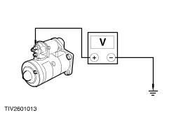
B1: CHECK THE BATTERY
1
Check the battery. REFER to Section  414-00 Charging System - General Information.

Is the battery OK?
Yes
No
INSTALL a new battery. REFER to Section  414-01 Battery, Mounting and Cables.TEST the system for normal operation.
B2: CHECK CONDITION OF PASSIVE ANTI-THEFT SYSTEM (PATS) SYSTEM
1
Observe the PATS warning indicator.

Does the indicator flash when attempting to start the vehicle?
Yes
Concern within the PATS system. REFER to Section  419-01A Anti-Theft - Active / 419-01B Anti-Theft - Passive.
No
B3: CHECK THE STARTER RELAY
1
Disconnect Starter Relay C52.
2
Carry out the relay component test.
REFER to Relay Test in this section.

Is the relay OK?
Yes
No
INSTALL a new starter relay. TEST the system for normal operation.
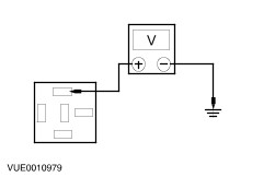
B4: CHECK SWITCHED POWER TO THE STARTER RELAY
1
Ignition switch in position III.

2
Measure the voltage between starter relay C52 pin 1, harness side and ground with the ignition key in position III.

Is the voltage greater than 10 volts?
Yes
Vehicles with manual transmission, GO to B8. .Vehicles with automatic transmission, GO to B9. .
No
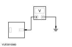
B5: CHECK SWITCHED POWER TO THE STARTER RELAY DIODE
1
Ignition switch in position 0.
2
Disconnect Starter Relay Diode C61.
3
Ignition switch in position III.

4
Measure the voltage between starter relay diode electrical C61 circuit 50-BB11 (GY/WH), harness side and ground with the ignition key in position III .

Is the voltage greater than 10 volts?
Yes
No
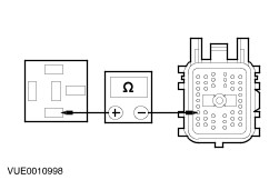
B6: CHECK BJB FOR OPEN
1
Ignition switch in position 0.

2
Measure the resistance between starter relay diode C61, circuit 50-BB11A (GY/WH), harness side and the starter relay C52 pin 1, circuit 50-BB11A (GY/WH), harness side.

Is the resistance less than 5 ohms?
Yes
INSTALL a new starter relay diode. TEST the system for normal operation.
No
INSTALL a new BJB. TEST the system for normal operation.
B7: CHECK CIRCUIT 50-BB11 FOR OPEN
1
Disconnect Ignition Switch C456.

2
Measure the resistance between ignition switch C456 pin 5, circuit 50-BB11 (GY/WH), harness side and diode C61 pin 1, harness side.

Is the resistance less than 5 ohms?
Yes
INSTALL a new ignition switch. REFER to Section  211-05 Steering Column Switches.TEST the system for normal operation.
No
REPAIR the circuit. TEST the system for normal operation.
B8: CHECK CIRCUIT 31S-BB12 (BK/YE) MANUAL TRANSMISSION
1
Disconnect In-line Connector C3001.

2
Measure the resistance between the starter relay C52 pin 2, 31S-BB12 (BK/YE), harness side and in-line connector C3001 male pin 36, circuit 31S-BB12 (BK/YE).

Is the resistance less than 5 ohms?
Yes
No
REPAIR circuit 31S-BB12 (BK/YE). TEST the system for normal operation.
B9: CHECK SIGNAL TO TRANSMISSION RANGE (TR) SENSOR AUTOMATIC TRANSMISSION
1
Disconnect TR Sensor C438.

2
Measure the resistance between the TR sensor C438 pin 4, circuit 31S-BB12 (BK/YE) and the starter relay C52 pin 2, circuit 31S-BB12 (BK/YE), harness side.

Is the resistance less than 5 ohms?
Yes
No
REPAIR circuit 31S-BB12 (BK/YE). TEST the system for normal operation.
B10: CHECK AUTOMATIC TRANSMISSON RANGE (TR) SENSOR FOR OPEN

1
Measure the resistance between TR sensor C438 pin 8, circuit 31S-TA9 (BK/GN), harness side and PCM C421 pin 82, harness side.

Is the resistance less than 5 ohms?
Yes
No
REPAIR the circuit. TEST the system for normal operation.
B11: CHECK TR SENSOR
NOTE:
NOTE:Place the transmission shift selector into the "P" position.

1
Measure the resistance between the TR sensor pin 4 and pin 8, component side.

Is the resistance less than 5 ohms?
Yes
No
INSTALL a new TR sensor. REFER to Section  307-01 Automatic Transmission/Transaxle.TEST the system for normal operation.

PINPOINT TEST C : THE ENGINE CRANKS SLOWLY

TEST CONDITIONS DETAILS/RESULTS/ACTIONS
C1: CHECK THE STARTER MOTOR LOAD
1
Carry out the starter motor load test on the starter motor.
REFER to Starter motor load in this section.

Is the starter motor OK?
Yes
No
INSTALL a new starter motor.
REFER to Starter Motor - 2.0L /
Starter Motor - 2.5L in this section.
TEST the system for normal operation.
C2: CHECK FOR VOLTAGE DROP

1
Measure the voltage between starter motor pin 30, component side and the positive battery terminal with the ignition key in position III.

Is the voltage less than 0.5 volts?
Yes
No
CLEAN and TIGHTEN all positive battery cable connections. TEST the system for normal operation. If the concern persists, INSTALL a new positive battery cable. REFER to Section  414-01 Battery, Mounting and Cables.TEST the system for normal operation.
C3: CHECK FOR GROUND CONNECTION

1
Measure the voltage between the starter motor case and battery negative terminal with the ignition key in the III (start) position.

Is the voltage less than 0.5 volts?
Yes
DIAGNOSE the battery and charging system. REFER to Section  414-00 Charging System - General Information.
No
CLEAN and TIGHTEN all negative battery cable connections, starter motor mounting and body to engine ground strap. TEST the system for normal operation. If the concern persists, INSTALL a new negative battery cable.

Component Tests

Starter Motor - Load

The battery must be fully charged before carrying out the Starter Motor Load Test. For battery inspection and testing. REFER to Section  414-00 Charging System - General Information.

  1. Set the parking brake and shift the transmission into NEUTRAL.
  1. Connect WDS and follow the on-screen instructions.

Starter Motor - No Load

  1. Remove the starter motor.
    REFER to Starter Motor - 2.0L /
    Starter Motor - 2.5L in this section.
  1. Connect WDS and follow on-screen instructions.

Component Tests

Relay Test

  1. Remove the relay.
  1. Using a fused jumper wire, connect one end to Terminal 85 of the relay. Connect the other end to ground.
  1. Using a second fused jumper wire, connect one end to Terminal 86 of the relay.
  1. Set the parking brake and shift the transmission into NEUTRAL.
  1. Connect WDS and follow the on-screen instructions.

Diagnosis and Testing|Removal and Installation > < Starting System - Vehicles Built Up To: 05-1999