1
-
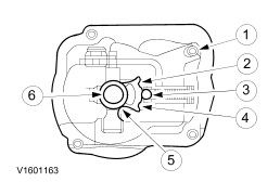
Transaxle housing, clutch side
The MTX-75 manual transaxle is a 2-shaft transaxle.
MTX-75 means:
- M: Manual
- T: Transmission
- X: Transaxle (front wheel drive)
- 75: Distance between input and output shaft in mm.
The aluminum transaxle housing comprises two closed sections. Additional reinforcement ribbing has been added to the transaxle housing to reduce noise and vibrations.
All the gear wheels in the "2-shaft transaxle" are in constant mesh. In each gear the required transaxle ratio is achieved by means of a pair of gear wheels.
When reverse gear is selected, an idler gear changes the direction of rotation of the output shaft.
The input and output shafts run in roller bearings.
To further improve stability and gear shifting, the selector mechanism has been revised to incorporate a maintenance-free cable operating mechanism.
All the gear wheels, including reverse gear, are bevel-cut, synchronized and run on needle roller bearings.
The first, second and third gears (vehicles built up to 08/2001) are dual-synchronized.
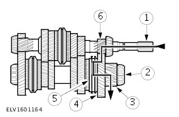
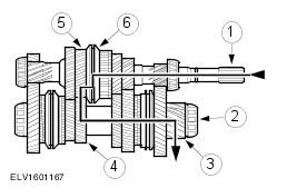
Input and Output Shaft
General View of the Input and Output Shaft
5
-
Third and fourth gear synchronizer
13
-
First and second gear synchronizer
18
-
Fifth and reverse gear synchronizer
In neutral, none of the gears are connected to the input or output shaft via the relevant synchronizer unit. No torque is transmitted to the differential.
The input and output shafts are each seated in one roller bearing in the transaxle housing section on the clutch side and one roller bearing in the transaxle housing section on the transaxle side.
The output drive pinion is in constant mesh with the differential drive annulus.
The third and fourth gear wheels and the third and fourth gear synchronizer are located on the input shaft. The gearing for first, second and reverse gears is an integral part of the input shaft.
The first, second, fifth and reverse gear wheels and the first and second gear synchronizer and fifth and reverse gear synchronizer are located on the output shaft. On vehicles built up to 07/2000 the gearing for third and fourth gear is an integral part of the output shaft.
Differential
The main components of the differential are:
- Output gear wheel
- Spur gear
- Four pinions at right angles to one another
- Differential housing with two roller bearings
The transaxle and differential are installed in a two-part aluminum housing which is flange-mounted to the engine.
The torque is transmitted from the spur gear to the halfshafts via two differential pinions mounted on the differential pinion shaft.
When cornering, the drive wheels need to turn at different speeds as the drive wheels travel different distances. This is achieved by means of the differential pinions which turn on their own shaft and mesh with the halfshaft pinions turning at different rates.
Power Flow
First Gear