| PINPOINT TEST A : THE SPEED CONTROL IS INOPERATIVE |
| TEST CONDITIONS | DETAILS/RESULTS/ACTIONS |
| A1: CHECK OPERATION OF THE HORN |
| | 1 Press the horn switches. |
| | Does the horn sound? Yes No |
| A2: CHECK ON SWITCH OPERATION |
| | 1 Disconnect Speed Control Actuator C833. |
| | 2 Measure the voltage between pin 5 and ground while pressing the ON switch. |
| | Is the voltage greater than 10 volts? Yes No INSTALL a new speed control switch. TEST the system for normal operation. |
| A3: CHECK SWITCH INPUT TO SPEED CONTROL ACTUATOR |
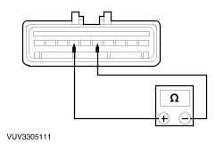
| | 1 Measure the resistance between the speed control actuator C833 pin 5, circuit 8-PG13 (WH), harness side and the speed control actuator C833 pin 6, circuit 31-PG13 (BK), harness side while pressing the OFF switch. |
| | Is the resistance less than 5 ohms? Yes No |
| A4: CHECK CIRCUIT 8-PG13 |
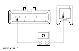
| | 1 Disconnect Airbag Sliding Contact C896. |
| | 2 Measure the resistance between the speed control actuator C833 pin 5, circuit 8-PG13 (WH), harness side and the air bag sliding contact C896 pin 3, circuit 8-PG13 (WH), harness side. |
| | Is the resistance less than 5 ohms? Yes No REPAIR circuit 8-PG13 TEST the system for normal operation. |
| A5: CHECK CONTINUITY OF AIR BAG SLIDING CONTACT |
| |
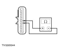
| | 1 Disconnect Speed Control Switch. |
| | 2 Measure the resistance between the air bag sliding contact connector, pin A (BK), component side, and the air bag sliding contact connector, pin 1 (BK), component side, and between the air bag sliding contact connector, pin B (RD/OG), component side, and the air bag sliding contact connector, pin 2 (RD/OG), component side, and between the air bag sliding contact connector, pin C (BK/BU), component side, and the air bag sliding contact connector, pin 3 (BK/BU), component side. |
| | Is the resistance less than 5 ohms? Yes INSTALL a new speed control switch. TEST the system for normal operation. No INSTALL a new air bag sliding contact. TEST the system for normal operation. |
| A6: CHECK CIRCUIT 91-PG12 |
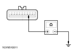
| | 1 Measure the resistance between the speed control actuator C833 pin 10, circuit 91-PG12 (BK/WH), harness side and ground. |
| | Is the resistance less than 5 ohms? Yes No REPAIR circuit 91-PG12. TEST the system for normal operation. |
| A7: CHECK CIRCUIT 14-PG12 |
| | 1 Ignition switch in position II. |
| | 2 Measure the voltage between the speed control actuator C833 pin 7, circuit 14-PG12 (VT/WH), harness side and ground. |
| | Is the voltage greater than 10 volts? Yes No REPAIR circuit 14-PG12. TEST the system for normal operation. |
| A8: CHECK BRAKE PEDAL POSITION (BPP) SWITCH INPUT TO ACTUATOR |
| | 1 Measure the voltage between the speed control actuator C833 pin 9, circuit 29S-PG16 (OG/YE), harness side and ground. |
| | Is the voltage greater than 10 volts? Yes No |
| A9: CHECK BRAKE PEDAL POSITION (BPP) SWITCH |
| | 1 Disconnect BPP Switch C824. |
| | 2 Measure the resistance between the BPP switch pin 1 and pin 2, component side, while pressing the switch plunger in and also with the plunger released. |
| | Are the resistances greater than 10,000 ohms with the plunger pressed and less than 5 ohms with the plunger released? Yes No INSTALL a new BPP switch. TEST the system for normal operation. |
| A10: CHECK CIRCUIT 29-PG6 (OG/YE) |
| | 1 Measure the voltage between the BPP switch C824 pin 1, circuit 29-PG6 (OG/YE), harness side and ground. |
| | Is the voltage greater than 10 volts? Yes No REPAIR circuit 29-PG6 (OG/YE). TEST the system for normal operation. |
| A11: CHECK CIRCUIT 29S-PG16 (OG/YE) |
| | 1 Measure the resistance between speed control actuator C833 pin 9, circuit 29-PG16 (OG/YE), harness side and BPP switch C824 pin 2, circuit 29S-PG16 (OG/YE) harness side. |
| | Is the resistance less than 5 ohms? Yes Adjust the BPP switch. TEST the system for normal operation No REPAIR circuit 29S-PG16 (OG/YE). TEST the system for normal operation. |
| A12: CHECK STOPLAMP SWITCH SIGNAL TO ACTUATOR |
| | 1 Measure the voltage between the speed control actuator C833 pin 4, circuit 29S-PG17 (OG/BU) , harness side and ground while depressing the brake pedal. |
| | Is the voltage greater than 10 volts ? Yes For vehicles with automatic transaxle. GO to A15. For vehicles with manual transaxle. GO to A13. No If the stoplamps operate correctly, REPAIR circuit 29S-PG17. TEST the system for normal operation. |
| A13: CHECK POWER TO CLUTCH PEDAL POSITION (CPP) SWITCH |
| | 1 Disconnect CPP Switch C825. |
| | 2 Measure the voltage between the CPP switch C825 pin 3, circuit 29S-PG7 (OG/BU), harness side and ground while depressing the brake pedal. |
| | Is the voltage greater than 10 volts? Yes No REPAIR circuit 29S-PG7. TEST the system for normal operation. |
| A14: CHECK CPP SWITCH |
| | 1 Measure the resistance between the CPP switch pin 1 and pin 3, component side. |
| | Is the resistance less than 5 ohms? Yes REPAIR circuit 29S-PG17. TEST the system for normal operation. No ADJUST or INSTALL a new CPP switch. TEST the system for normal operation. |
| A15: CHECK VEHICLE SPEED SENSOR (VSS) SIGNAL TO ACTUATOR |
| | 1 Disconnect Instrument Cluster C606. |
| | 2 Measure the resistance between the instrument cluster C606 pin 26, circuit 8GB8 (WH/BU), harness side and the speed control actuator C833 pin 3, circuit 8PG18. |
| | Is the resistance greater than 10,000 ohms? Yes REPAIR circuit 8PG18/8GB8. Test the system for normal operation. No If there are no DTCs. INSTALL a new speed control actuator. TEST the system for normal operation. |