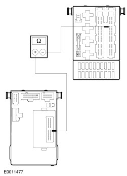
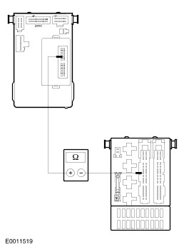
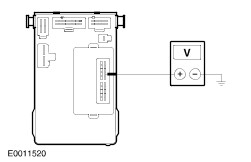
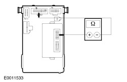
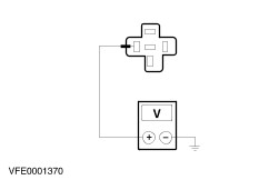
| Diagnosis and Testing Refer to Wiring Diagrams Section 419-10, for schematic and connector information. Special Tool(s) | | Terminal probe kit 29 - 011A | Principles of Operations The Cougar has a central timer module (CTM) which monitors and controls various time based functions. Depending on the equipment of the vehicle the CTM has several functions: Controlling the time dependent operation of the heated rear window. Controlling the time dependent operation of the interior lights. Controlling the timing of the intermittent operation of the wipers. Emitting an acoustic warning if the driver's door is opened and the headlamps are still on. Emitting a warning signal if the driver's seat belt buckle is not engaged. The CTM is plugged into the Central Junction Box (CJB) from below. The electrical connections for the 20 pin connector are also made at the same time. Incorporating the most important time base control functions in the CTM allows perfectly normal working current relays to be used for the power supply of the systems mentioned previously. These relays are then actuated by the CTM. The CTM has its own diagnostic modes. Full diagnostic includes the inputs and outputs of the CTM. | Pin Number | Circuit | Circuit Function | | 1 | - | Input passenger side (ground signal) | | 2 | - | Input driver side (ground signal) | | 3 | - | Input wiper/washer switch (ground or power signal) | | 4 | - | Input rear window heater switch (ground signal from switch) | | 5 | - | Not connected | | 6 | - | Ignition switch (power signal) | | 7 | - | Input parking lamp switch (power signal) | | 8 | - | Input key in switch (power signal) | | 9 | - | Output illumination entry relay (ground relay) | | 10 | - | Output seat belt warning lamp (ground signal) | | 11 | - | Output intermittent wiper relay (ground signal) | | 12 | - | Output rear window heater relay (ground signal) | | 13 | - | Input park position switch of the front wiper motor (ground or power signal) | | 14 | - | Input intermittent wiper/washer switch (power signal) | | 15 | - | Input, seat belt warning (ground signal) | | 16 | - | Ground | | 17 | - | Input wiper rate rheostat/select (power signal from variable resistor) | | 18 | - | Battery | | 19 | - | Input from door lock module | | 20 | - | Not connected | Inspection and Verification - Verify the customers concern by operating the system.
- Visually inspect for obvious signs of mechanical or electrical damage.
Visual Inspection Chart | Electrical | - Fuse(s).
- Central timer module (CTM).
- Central Junction Box (CJB).
- Relay(s).
- Switch(es).
- Electrical connector(s).
- Wiring harness.
| - If an obvious cause for an observed or reported concern is found, correct the cause (if possible) before proceeding to the next step.
- If the cause is not visually evident, verify the symptom and refer to the Symptom Chart.
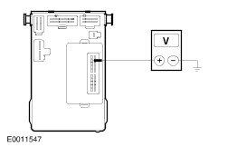
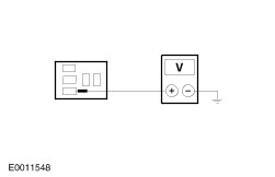
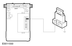
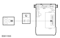
The memory of the CTM contains a self - test program which enables most inputs and outputs from the module to be tested. The following inputs cannot be tested by means of the self - test procedure: Ignition switch signal inputs. Intermittent wipe controller. Remote release. Ignition key sensor. The self - test itself is divided into the diagnosis mode for input signals and the diagnosis mode for the output signals. The two diagnosis modes are activated by pressing the heated rear window switch (for details refer to the chapter self - test below) and switching the ignition switch to the "ON" position. If this button is faulty, the self - test mode cannot be activated. The self - test can be interrupted by switching the ignition off and on. This causes the CTM to revert to its original settings. Symptom Chart Symptom Chart | Symptom | Possible Sources | Action | | Central Timer Module (CTM) is inoperative | * Open/short circuits (e.g. wiring, fuses, CTM or CJB). | * GO to Pinpoint Test A. | | Diagnosis mode is not activated | * Open/short circuits (e.g. wiring, rear window heater switch, CTM or CJB). | * GO to Pinpoint Test B. | | No acoustic signal by unfastened driver seat belt and ignition on | * Open/short circuits (e.g. wiring, seat belt switch, CTM or CJB). | * GO to Pinpoint Test C. | | Interior lights are inoperative | * Open/short circuits (e.g. wiring, door switch, CTM or CJB). | * GO to self - test. | | No acoustic signal by lights on and opened driver door | * Open/short circuits (e.g. wiring, light switch, CTM or CJB). | * GO to Pinpoint Test E. | | The wash and wipe function does not operate correctly, front | * Open/short circuits (e.g. wiring, front wiper relay, wiper/washer switch, CTM or CJB). | * GO to self - test | | The intermittent wiper speed does not operate correctly | * Open/short circuits (e.g. wiring, front wiper relay, wiper/washer switch, CTM or CJB). | * GO to self - test | | The rear window heater is inoperative | * Open/short circuits (e.g. wiring, rear window heater, rear window heater relay, CTM or CJB). | * GO to Pinpoint Test H. | | Seat belt warning light is inoperative | * Open/short circuits (e.g. wiring, instrument cluster, CTM or CJB). | * GO to Pinpoint Test J. | SELF - TEST The self - test procedure must be carried out in order indicated below. Conditions: Switch "OFF" the ignition. Switch "OFF" all electrical loads. Set the interior light switch to 12 sec. Apply the handbrake. Select neutral in the case of manual transmission, select park position "P" in the case of automatic transmission. Close all doors. Do not operate the door handles. Fasten the driver seat belt. The input diagnosis mode will be activated as follows: Keep the button for the heated rear window pressed. Switch the ignition to the "ON"position. Release the button for the heated rear window. SELF - TEST TABLE | SELF - TEST Operation | Action in event of fault | | If the input signal diagnosis mode is not activated. | GO to Pinpoint Test B | | Unfasten the seat belt and fasten it again. The acoustic signal should sound when the seat belt is unfastened. | GO to Pinpoint Test C | | Open and close the driver door. When the door is open the CTM should produce an acoustic signal. | GO to Pinpoint Test D | | Open and close the passenger door. When the door is open the CTM should produce an acoustic signal. | GO to Pinpoint Test D | | Switch the parking lamps and driving lights to the "ON" and "OFF" position. The acoustic signal should sound when the lights are switched on. | GO to Pinpoint Test E | | Switch the front washer system to the "ON" and "OFF" position. The acoustic signal should sound when the washer system is switched on. | GO to Pinpoint Test F | | Output signal diagnosis. | - | | To activate the output signal diagnosis mode, switch the wiper/washer switch to the intermittent wipe mode. The CTM inputs and outputs are now deactivated. | - | | Briefly press the button for the heated rear window. The windshield wiper will be activated. The acoustic signal should sound each time the wiper reaches its park position. Press the heated rear window button, then the windshield wiper will be switched "OFF" again. | GO to Pinpoint Test G | | Briefly press the button for the heated rear window. The heated rear window will be activated, use a multimeter to check for current in the heating wires. Press the heated rear window button and then the heated rear window will be switched "OFF" again. | GO to Pinpoint Test H | | Briefly press the button for the heated rear window. The interior lights will be switched "ON". Press the heated rear window button, then the interior lights will be switched "OFF" again. | GO to Pinpoint Test I | | Briefly press the button for the heated rear window. The seat belt warning light in the instrument cluster should illuminate. Press the heated rear window button, then the warning light will go "OFF" again. | GO to Pinpoint Test J | | Set the wiper/washer switch to "OFF" position. Switch the ignition to the "OFF" position. The CTM will now operate in normal mode. | - | Pinpointtests | PINPOINT TEST A : CENTRAL TIMER MODULE (CTM) IS INOPERATIVE | | TEST CONDITIONS | DETAILS/RESULTS/ACTIONS | | A1: CHECK THE CTM FOR VOLTAGE | | | 1 Ignition switch in position 0. | | | 2 Disconnect CTM C23 (CJB). | | | 3 Ignition switch in position II. | | | 4 Measure the voltage between CTM, connector C23, pin 18, CJB side and ground. | | | Is battery voltage indicated? Yes No REPAIR the CJB. TEST the system for normal operation. | | A2: CHECK THE CTM FOR GROUND | | | 1 Measure the voltage between CTM, connector C23, pin 18 and pin 16, CJB side. | | | Is battery voltage indicated? Yes INSTALL a new CTM. TEST the system for normal operation. No | | A3: CHECK THE CJB | | | 1 Ignition switch in position 0. | | | 2 Disconnect CJB C361. | | | 3 Measure the resistance between CTM, connector C23, pin 16, CJB side and CJB, connector C361, pin 10, component side. | | | Is the resistance less than 2 ohms? Yes REPAIR circuit 31 - FA23 (BK). TEST the system for normal operation. No REPAIR the CJB. TEST the system for normal operation. | | PINPOINT TEST B : DIAGNOSIS MODE IS NOT ACTIVATED | | TEST CONDITIONS | DETAILS/RESULTS/ACTIONS | | B1: CHECK THE CTM FOR VOLTAGE | | | 1 Ignition switch in position 0. | | | 2 Disconnect CTM C23 (CJB). | | | 3 Ignition switch in position II. | | | 4 Measure the voltage between CTM, connector C23, pin 6, CJB side and ground. | | | Is battery voltage indicated? Yes No | | B2: CHECK THE CJB | | | 1 Ignition switch in position 0. | | | 2 Disconnect CJB C372. | | | 3 Measure the resistance between CTM, connector C23, pin 6, CJB side and CJB, connector C372, pin 7, component side. | | | Is the resistance less than 2 ohms? Yes REPAIR circuit 15 - DA1 (GN/YE) or 15 - DA2 (GN/BU) by using the wiring diagrams. TEST the system for normal operation. No REPAIR the CJB. TEST the system for normal operation. | | B3: CHECK THE REAR WINDOW HEATER SWITCH | | | 1 Ignition switch in position 0. | | | 2 Measure the resistance between CTM, connector C23, pin 16 and pin 4, CJB side. Press and hold the rear heater switch during the measurement. | | | Is the reasistance less than 2 ohms? Yes INSTALL a new CTM. TEST the system for normal operation. No | | B4: CHECK CIRCUIT 31S - HB29 (BK/WH) FOR OPEN | | | 1 Ignition switch in position 0. | | | 2 Disconnect CJB C364. | | | 3 Measure the resistance between CJB, connector C364, pin 5, circuit 31S - HB29 (BK/WH), harness side and ground. Press and hold the rear window heater switch during the measurement. | | | Is the resistance less than 2 ohms? Yes REPAIR the CJB. TEST the system for normal operation. No | | B5: CHECK CIRCUIT 31S - HB29 (BK/WH) FOR OPEN | | | 1 Ignition switch in position 0. | | | 2 Disconnect Rear window heater switch C437. | | | 3 Measure the resistance between CJB, connector C364, pin 5, circuit 31S - HB29 (BK/WH), harness side and rear window heater switch, connector C437, pin 2, circuit 31S - HB29 (BK/WH), harness side. | | | Is the resistance less than 2 ohms? Yes No REPAIR circuit 31S - HB29 (BK/WH) by using the wiring diagrams. TEST the system for normal operation. | | B6: CHECK THE CIRCUIT 31 - HB22 (BK) FOR OPEN | | | 1 Measure the resistance between rear window heater switch, connector C437, pin 1, circuit 31 - HB22 (BK), harness side and ground. | | | Is the resistance less than 2 ohms? Yes INSTALL a new rear window heater switch. TEST the system for normal operation. No REPAIR circuit 31 - HB22 (BK) by using the wiring diagrams. TEST the system for normal operation. | | PINPOINT TEST C : NO ACOUSTIC SIGNAL BY UNFASTENED DRIVER SEAT BELT AND IGNITION ON | | TEST CONDITIONS | DETAILS/RESULTS/ACTIONS | | C1: CHECK CIRCUIT 31S - GE52 (BK/RD) FOR OPEN | | | 1 Ignition switch in position 0. | | | 2 Disconnect CTM C23 (CJB). | | | 3 Fasten the driver seat belt. | | | 4 Measure the resistance between CTM, connector C23, pin 15, CJB side and ground. | | | Is the resistance less than 2 ohms? Yes INSTALL a new CTM. TEST the system for normal operation. No | | C2: CHECK CIRCUIT 31S - GE52 (BK/RD) FOR OPEN | | | 1 Ignition switch in position 0. | | | 2 Disconnect CJB C366. | | | 3 Measure the resistance between CJB, connector C366, pin 1, circuit 31S - GE52 (BK/RD), harness side and ground. | | | Is the resistance less than 2 ohms? Yes REPAIR the CJB. TEST the system for normal operation. No | | C3: CHECK CIRCUIT 31S - GE52 (BK/RD) FOR OPEN | | | 1 Ignition switch in position I. | | | 2 Disconnect Safty belt buckle switch C109/C1008. | | | 3 Measure the resistance between CJB, C366, pin 1, circuit 31S - GE52 (BK/RD), harness side and safety belt buckle switch, connector C109 (before 03/99) respectively C1008 (since 03/99), pin 2 circuit 31S - GE52 (BK/RD), harness side. | | | Is the resistance less than 2 ohms? Yes No REPAIR circuit 31S - GE52 (BK/RD) by using the wiring diagrams. TEST the system for normal operation. | | C4: CHECK THE SEAT BELT BUCKLE SWITCH | | | 1 Ignition switch in position 0. | | | 2 Fasten the driver seat belt. | | | 3 Measure the resistance between seat belt buckle switch, connector C109 (before 03/99) respectively C1008 (since 03/99), pin 1 and pin 2, component side. | | | Is the resistance less than 2 ohms? Yes REPAIR the circuit 31 - GE52 (BK) by using the wiring diagrams. TEST the system for normal operation. No INSTALL a new seat belt buckle switch. TEST the system for normal operation. | | PINPOINT TEST D : INTERIOR LIGHTS ARE INOPERATIVE | | TEST CONDITIONS | DETAILS/RESULTS/ACTIONS | | D1: DETERMINE THE FUNCTION OF THE SWITCHES | | | 1 Determine the proper function of the driver's side door switch. | | | Does the door switch operate on the driver's side in the self - test? Yes No | | D2: DETERMINE THE FUNCTION OF THE SWITCH | | | 1 Ignition switch in position II. | | | 2 Open the passenger's side door. Watch the”door open" indicator lamp in the instrument cluster. | | | Does the lamp illuminate? Yes No | | D3: CHECK THE CJB | | | 1 Ignition switch in position 0. | | | 2 Disconnect CJB C366. | | | 3 Disconnect CTM C23 (CJB). | | | 4 Measure the resistance between CJB, connector C366, pin 9, CJB side and CTM, connector C23, pin 1, CJB side. | | | Is the resistance less than 2 ohms? Yes INSTALL a new CTM. TEST the system for normal operation. No REPAIR the CJB. TEST the system for normal operation. | | D4: CHECK CIRCUIT 31S - LC30 (BK/GN) FOR OPEN | | | 1 Ignition switch in position 0. | | | 2 Disconnect CJB C366. | | | 3 Disconnect Front door switch C684 (RH). | | | 4 Measure the resistance between CJB, connector C366, pin 9, circuit 31S - LC30 (BK/GN) harness side and front door switch, connector C684, pin 1, harness side. | | | Is the resistance less than 2 ohms? Yes No REPAIR circuit 31S - LC30 (BK/GN) by using the wiring diagrams. TEST the system for normal operation. | | D5: CHECK THE DOOR SWITCH | | | 1 Measure the resistance of the front door switch, connector C684 (LH) or connector C685 (RH), between pin 1 and pin 2, component side. Keep the front door switch pressed during measurement. | | | Is the resistance less than 2 ohms? Yes REPAIR the circuit 31 - LC21 (BK) by using the wiring diagrams. TEST the system for normal operation. No INSTALL a new front door switch. TEST the system for normal operation. | | D6: DETERMINE THE FUNCTION OF THE SWITCH | | | 1 Ignition switch in position II. | | | 2 Open the driver's door. Watch the”door open" indicator lamp in the instrument cluster. | | | Does the indicator lamp illuminate? Yes No | | D7: CHECK THE CJB | | | 1 Ignition switch in position 0. | | | 2 Disconnect CJB C366. | | | 3 Disconnect CTM C23 (CJB). | | | 4 Measure the resistance between CJB, connector C366, pin 2, CJB side and CTM, connector C23, pin 2, CJB side. | | | Is the resistance less than 2 ohms? Yes INSTALL a new CTM. TEST the system for normal operation. No REPAIR the CJB. TEST the system for normal operation. | | D8: CHECK CIRCUIT 31S - LC29 (BK/RD) FOR OPEN | | | 1 Ignition switch in position 0. | | | 2 Disconnect CJB C366. | | | 3 Disconnect Front door switch: C685 (LH), C684 (RH). | | | 4 Measure the resistance between CJB, connector C366, pin 2, circuit 31S - LC29 (BK/RD) harness side and front door switch, connector C684 (LH) or connector C685 (RH), pin 1, harness side. | | | Is the resistance less than 2 ohms? Yes No REPAIR the circuit 31S - LC29 (BK/RD) by using the wiring diagrams. TEST the system for normal operation. | | D9: CHECK THE DOOR SWITCH | | | 1 Connect CJB C366. | | | 2 Measure the resistance of the front door switch, connector C685 (LH) or connector C684 (RH), pin 1 and pin 2 component side. Keep the front door switch pressed during measurement. | | | Is the resistance less than 2 ohms? Yes REPAIR the circuit 31 - LC9 (BK) by using the wiring diagrams. TEST the system for normal operation. No INSTALL a new front door switch. TEST the system for normal operation. | | PINPOINT TEST E : NO ACOUSTIC SIGNAL BY LIGHTS ON AND OPENED DRIVER DOOR | | TEST CONDITIONS | DETAILS/RESULTS/ACTIONS | | E1: DETERMINE THE FUNCTION OF THE EXTERIOR LIGHTING | | | 1 Ignition switch in position II. | | | 2 Turn the lamp switch to the”ON" position. | | | Are the licence plate lamps illuminated? Yes No | | E2: CHECK THE CJB | | | 1 Ignition switch in position 0. | | | 2 Disconnect CJB C361. | | | 3 Disconnect CTM C23 (CJB). | | | 4 Measure the resistance between CJB, connector C361, pin 4, CJB side and CTM, connector C23, pin 7, CJB side. | | | Is the resistance less than 2 ohms? Yes INSTALL a new CTM. TEST the system for normal operation. No REPAIR the CJB. TEST the system for normal operation. | | PINPOINT TEST F : NO ACOUSTIC SIGNAL IF THE WASHER SWITCH IS ON | | TEST CONDITIONS | DETAILS/RESULTS/ACTIONS | | F1: CHECK THE CJB | | | 1 Ignition switch in position 0. | | | 2 Disconnect CJB C369. | | | 3 Disconnect CTM C23 (CJB). | | | 4 Measure the resistance between CJB, connector C369, pin 7, CJB side and CTM, connector C23, pin 3, CJB side. | | | Is the resistance less than 2 ohms? Yes INSTALL a new CTM. TEST the system for normal operation. No REPAIR the CJB. TEST the system for normal operation. | | PINPOINT TEST G : THE INTERMITTENT WIPER SPEED DOES NOT OPERATE CORRECTLY | | TEST CONDITIONS | DETAILS/RESULTS/ACTIONS | | G1: CHECK THE VARIABLE INTERMITTENT WIPER POTENTIOMETER | | | 1 Ignition switch in position 0. | | | 2 Disconnect CTM C23 (CJB). | | | 3 Measure the resistance between CTM, connector C23, pin 14 and pin 17, CJB side. Switch the variable intermittent wiper potentiometer from position 1 to 6 on the multifunction switch. | | | Is the resistance between 1 kohms and 47 kohms? Yes No | | G2: CHECK CIRCUIT 8 - KA18 (WH) FOR OPEN | | | 1 Ignition switch in position 0. | | | 2 Disconnect CTM C23 (CJB). | | | 3 Disconnect Wiper washer switch C441. | | | 4 Measure the resistance between CTM, connector C23, pin 17, circuit 8 - KA18 (WH), CJB side and multifunction switch, connector C441, pin 6, circuit 8 - KA18 (WH), harness side. | | | Is the resistance less than 2 ohms? Yes No | | G3: CHECK THE CJB | | | 1 Ignition switch in position 0. | | | 2 Connect Wiper/washer switch C441. | | | 3 Disconnect CJB C372. | | | 4 Measure the resistance between CTM, connector C23, pin 17, CJB side and CJB, connector C372, pin 3, CJB side. | | | Is the resistance less than 2 ohms? Yes REPAIR circuit 8 - KA18 (WH) by using the wiring diagrams. TEST the system for normal operation. No REPAIR the CJB. TEST the system for normal operation. | | G4: CHECK CIRCUIT 8 - KA19 (WH/BK) FOR OPEN | | | 1 Measure the resistance between CTM, connector C23, pin 14, CJB side and wiper washer switch, connector C441, pin 5, circuit 8 - AK19 (WH/BK), harness side. | | | Is the resistance less than 2 ohms? Yes INSTALL a new wiper/washer switch. TEST the system for normal operation. No | | G5: CHECK THE CJB | | | 1 Ignition switch in position 0. | | | 2 Connect Wiper/washer switch C441. | | | 3 Disconnect CJB C372. | | | 4 Measure the resistance between CTM, connector C23, pin 14, CJB side and CJB, connector C372, pin 4, CJB side. | | | Is the resistance less than 2 ohms? Yes REPAIR the circuit 8 - KA19 (WH/BK) by using the wiring diagrams. TEST the system for normal operation. No REPAIR the CJB. TEST the system for normal operation. | | G6: CHECK THE WIPER DELAY CONTROL SWITCH | | | 1 Ignition switch in position II. | | | 2 Measure the voltage between CTM, connector C23, pin 14, CJB side and ground. Turn the wiper washer switch to the”Interval" position. | | | Is battery voltage indicated? Yes No INSTALL a new wiper/washer switch. TEST the system for normal operation. | | G7: CHECK THE WIPER MOTOR IN PARK POSITION | | | 1 Measure the voltage between CTM, connector C23, pin 13, CJB side and ground. Turn the wiper/washer switch to the "normal wipe" position. | | | Is battery voltage indicated during wiping and no voltage in park position? Yes No | | G8: CHECK THE CJB | | | 1 Ignition switch in position 0. | | | 2 Disconnect CJB C369. | | | 3 Measure the resistance between CTM, connector C23, pin 13, CJB side and CJB. connector C369, pin 4, CJB side. | | | Is the resistance less than 2 ohms? Yes CHECK the wiper motor, refer to the component test in section 501 - 16. No REPAIR the CJB. TEST the system for normal operation. | | G9: CHECK THE FRONT WIPER RELAY | | | 1 Ignition switch in position II. | | | 2 Measure the voltage between CTM, connector C23, pin 11, CJB side and ground. | | | Is battery voltage indicated? Yes No | | G10: CHECK THE CJB | | | 1 Ignition switch in position 0. | | | 2 Disconnect Windshield wiper relay C72 (CJB). | | | 3 Ignition switch in position II. | | | 4 Measure the voltage between windshield wiper relay, connector C72, pin 2, CJB side and ground. | | | Is battery voltage indicated? Yes No REPAIR the CJB. TEST the system for normal operation. | | G11: CHECK THE CJB | | | 1 Ignition switch in position 0. | | | 2 Measure the resistance between windshield wiper relay, connector C72, pin 1, CJB side and CTM, connector C23, pin 11, CJB side. | | | Is the resistance less than 2 ohms? Yes INSTALL a new windshield wiper relay. TEST the system for normal operation. No REPAIR the CJB. TEST the system for normal operation. | | G12: CHECK THE CJB | | | 1 Ignition switch in position 0. | | | 2 Disconnect Windshield wiper relay C72 (CJB). | | | 3 Ignition switch in position II. | | | 4 Measure the voltage between windshield wiper relay, connector C72, pin 5, CJB side and ground. | | | Is battery voltage indicated? Yes INSTALL a new CTM. TEST the system for normal operation. No REPAIR the CJB. TEST the system for normal operation. | | PINPOINT TEST H : THE REAR WINDOW HEATER IS INOPERATIVE | | TEST CONDITIONS | DETAILS/RESULTS/ACTIONS | | H1: CHECK THE REAR WINDOW HEATER RELAY | | | 1 Ignition switch in position 0. | | | 2 Disconnect CTM C23 (CJB). | | | 3 Ignition switch in position II. | | | 4 Measure the voltage between CTM, connector C23, pin 12, CJB side and ground. | | | Is battery voltage indicated? Yes No | | H2: CHECK THE CJB | | | 1 Ignition switch in position 0. | | | 2 Disconnect Rear window heater relay C56 (CJB). | | | 3 Ignition switch in position II. | | | 4 Measure the voltage between rear window heater relay, connector C56, pin 2, CJB side and ground. | | | Is battery voltage indicated? Yes No REPAIR the CJB. TEST the system for normal operation. | | H3: CHECK THE CJB | | | 1 Ignition switch in position 0. | | | 2 Disconnect CTM C23 (CJB). | | | 3 Measure the resistance between rear window heater relay, connector C56, pin 1 CJB side and CTM, connector C23, pin 12, CJB side. | | | Is the resistance less than 2 ohms? Yes INSTALL a new relay. TEST the system for normal operation. No REPAIR the CJB. TEST the system for normal operation. | | H4: CHECK THE CJB | | | 1 Ignition switch in position 0. | | | 2 Disconnect Rear window heater relay C56 (CJB). | | | 3 Ignition switch in position II. | | | 4 Measure the voltage between rear window heater relay, connector C56, pin 3, CJB side and ground. | | | Is battery voltage indicated? Yes No REPAIR the CJB. TEST the system for normal operation. | | H5: CHECK CIRCUIT 15S - HB19 (GN/BU) | | | 1 Ignition switch in position 0. | | | 2 Disconnect Fuse F19 (CJB). | | | 3 Measure the resistance between rear window heater relay, connector C56, pin 5, circuit 15S - HB19 (GN/BU), CJB side and ground. | | | Is the resistance less than 10 ohms? Yes INSTALL a new rear window heater relay. TEST the system for normal operation. No | | H6: CHECK THE CJB | | | 1 Disconnect CJB C368. | | | 2 Measure the resistance between rear window heater relay, connector C56, pin 5, CJB side and CJB, connector C368, pin 1, component side. | | | Is the resistance less than 2 ohms? Yes No If fuse F29 is OK, REPAIR the CJB. TEST the system for normal operation. | | H7: CHECK THE REAR WINDOW HEATER | | | 1 Ignition switch in position 0. | | | 2 Disconnect Rear window heater C1891. | | | 3 Measure the resistance between rear window heater, C1891, component side and ground. | | | Is the resistance less than 10 ohms? Yes REPAIR circuit 15S - HB19 (GN/BU) by using the wiring diagrams. TEST the system for normal operation. No INSTALL a new rear heater window. TEST the system for normal operation. | | PINPOINT TEST I : INTERIOR LIGHTS ARE INOPERATIVE | | TEST CONDITIONS | DETAILS/RESULTS/ACTIONS | | I1: CHECK THE INTERIOR LAMP RELAY FOR VOLTAGE | | | 1 Ignition switch in position 0. | | | 2 Disconnect CTM C23 (CJB). | | | 3 Measure the voltage between CTM, connector C23, pin 9, CJB side and ground. | | | Is battery voltage indicated? Yes No | | I2: CHECK THE CJB | | | 1 Ignition switch in position 0. | | | 2 Disconnect Interior lamp relay C57 (CJB). | | | 3 Ignition switch in position II. | | | 4 Measure the voltage between interior lamp relay, connector C57, pin 2, CJB side and ground. | | | Is battery voltage indicated? Yes No REPAIR the CJB. TEST the system for normal operation. | | I3: CHECK THE CJB | | | 1 Ignition switch in position 0. | | | 2 Measure the resistance between interior lamp relay, connector C57, pin 1, CJB side and CTM, connector C23, pin 9, CJB side. | | | Is the resistance less than 2 ohms? Yes INSTALL a new interior lamp relay. TEST the system for normal operation. No REPAIR the CJB. TEST the system for normal operation. | | I4: CHECK THE CTM | | | 1 Ignition switch in position II. | | | 2 Use a fused (fuse 7.5 A) jumper wire and connect between CTM, connector C23, pin 9, CJB side and ground. SET the interior lamp switch to 12 sec. | | | Is the interior light illuminated? Yes INSTALL a new CTM. TEST the system for normal operation. No | | I5: CHECK THE CJB | | | 1 Disconnect Interior light relay C57 (CJB). | | | 2 Measure the voltage between interior lamp relay, connector C57, pin 3, CJB side and ground. SET the interior lamp switch to 12 sec. | | | Is battery voltage indicated? Yes No | | I6: CHECK THE CJB | | | 1 Ignition switch in position 0. | | | 2 Disconnect CJB C367. | | | 3 Measure the resistance between interior light relay, connector C57, pin 3, CJB side and CJB, connector C367, pin 3, CJB side. | | | Is the resistance less than 2 ohms? Yes REPAIR circuit 31S - LB13 (BK/BU) by using the wiring diagrams. TEST the system for normal operation. No REPAIR the CJB. TEST the system for normal operation. | | I7: CHECK THE CJB | | | 1 Measure the resistance between interior lamp relay, connector C57, pin 5, CJB side and CTM, connector C23, pin 16, CJB side. | | | Is the resistance less than 2 ohms? Yes INSTALL a new interior lamp relay. TEST the system for normal operation. No REPAIR the CJB. TEST the system for normal operation. | | PINPOINT TEST J : SEAT BELT WARNING LIGHT IS INOPERATIVE | | TEST CONDITIONS | DETAILS/RESULTS/ACTIONS | | J1: CHECK THE INSTRUMENT CLUSTER | | | 1 Ignition switch in position 0. | | | 2 Disconnect CTM C23 (CJB). | | | 3 Ignition switch in position II. | | | 4 Use a fused (fuse 7.5 A) jumper wire and connect between CTM, connector C23, pin 10, CJB side and ground. | | | Is the seat belt warning light illuminated? Yes INSTALL a new CTM. TEST the system for normal operation. No | | J2: CHECK THE CJB | | | 1 Ignition switch in position 0. | | | 2 Disconnect CJB C362. | | | 3 Measure the resistance between CTM, connector C23, pin 10, CJB side and CJB, connector C362, pin 1, component side. | | | Is the resistance less than 2 ohms? Yes No REPAIR the CJB. TEST the system for normal operation. | | J3: CHECK CIRCUIT 31S - GE49 (BK/BU) FOR OPEN | | | 1 Disconnect Instrument cluster C808b. | | | 2 Measure the resistance between CJB, C362, pin 1, circuit 31S - GE49 (BK/BU), harness side and instrument cluster, connector C808b, pin 18, circuit 31S - GE49 (BK/BU), harness side. | | | Is the resistance less than 2 ohms? Yes INSTALL a new instrument cluster. TEST the system for normal operation. No REPAIR circuit 31S - GE49 (BK/BU) by using the wiring diagrams. TEST the system for normal operation. | |