| Diagnosis and Testing Refer to Wiring Diagrams Section 501-14, for schematic and connector information. Special Tool(s) | | 73 Digital Multimeter 105 - R0051 or equivalent | Principles of Operations The Door Switch Lock Function When a door lock switch is moved into the lock position or a door lock cylinder is rotated to the lock position, the door lock switch grounds the lock circuit input to the central security module (CSM). The CSM then provides 12 volts to one side of the door lock actuators contained in the door latch unit and simultaneously grounds the other side of the door lock actuators. This completes the door lock actuator circuit, causing the door lock actuators to rotate a cam assembly, which then locks the doors. The 12 volts that the CSM provides to the door lock actuators are provided to both door lock actuators from a single pin on the CSM connector. The Door Switch Unlock Function When a door lock switch is moved into the unlock position, the door lock switch grounds the unlock circuit input to the CSM. The CSM then provides 12 volts to the opposite side (relative to locking the door) of the door lock actuator(s) contained in the door latch unit and simultaneously grounds the other side of the door lock actuator(s). This completes the door lock actuator circuit, causing the door lock actuator(s) to rotate a cam assembly in the opposite direction, which the unlocks the door(s). The 12 volts which the CSM provides to the door lock actuator(s) are provided to each door lock actuator from the individual pins on the CSM connector. The Liftgate Release When the liftgate release switch is depressed, it grounds an input circuit to the CSM. When the CSM senses the ground, it sends 12 volts to cycle the liftgate release actuator. Door Lock Cylinder Functions Both the driver and passenger doors can be locked from either door lock cylinder. When the ignition key is inserted into either door lock and is rotated into the lock position, the linkage moves to rotate a cam in the door latch unit. When the cam in the door latch rotates, it mechanically moves the door latch (in the door in which the key is being used) into the locked position. The other door is locked electronically. As the cam in the door latch unit rotates to mechanically lock the first door, it also closes a switch in that door latch unit that grounds an input to the CSM. This causes the CSM to send 12 volts to one side and grounds the other side of the door lock actuator, which then rotates its cam assembly, locking the remaining door. Only one door can be unlocked from any one door lock cylinder. When the ignition key is inserted into a door lock cylinder and is rotated into the unlock position, the linkage moves to rotate a cam in the door latch unit. When the cam in the door latch unit rotates, it mechanically moves the door latch into the unlocked position. Self - Test This module is equipped with a manually activated self - test. When self - test is activated the central security module (CSM) will give visual and audible response every time an input signal is received from an actuator. To activate the self - test mode, press the hood switch seven times within six seconds. Once the CSM has entered self - test mode, the module will sound the horn and flash the turn signal lamps once to acknowledge the input. The following are inputs to the CSM that can be tested while the CSM is in self - test mode: - Remote transmitter
- Hood switch
- Driver door entry switch
- Passenger door entry switch
- Liftgate entry switch
- Driver door lock motor set/reset switch
- Passenger door lock motor set/reset switch
- Liftgate anti - theft inhibit switch
- Integrated lock/unlock switches within power door lock actuator
Inspection and Verification -
NOTE:Make sure that the battery is fully charged before starting electrical diagnosis. NOTE:Prior to carrying out the CSM Self - Test, make sure that both the driver and passenger doors are open. Verify the customer concern by operating the system. - Visually inspect for obvious signs of mechanical and electrical damage.
Visual Inspection Chart | Mechanical | Electrical | - Binding latch mechanisms
- Binding linkage
- Misaligned door
| - Central junction box fuse 25 (20A)
- Damaged wiring harness
- Loose or corroded connection(s)
- Circuit
- Door lock switch
- Door lock actuator
| - If an obvious cause for an observed or reported concern is found, correct the cause (if possible) before proceeding to the next step.
- If concern remains after the inspection, use FDS 2000 to diagnose system.
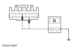
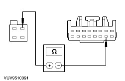
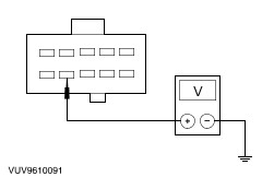
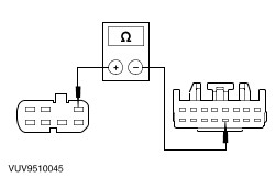
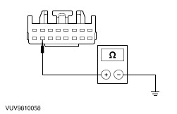
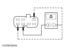
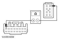
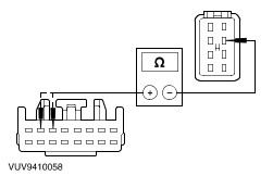
Central Security Module (CSM) Datalogger Signal Index | Signal | Description | Expected Value | | ATI_SW | Tailgate anti - theft inhibit switch status | ON, OFF | | DRV_AJAR | Driver door ajar | OPEN, CLOSED | | T_AJAR | Tailgate/hatch ajar | OPEN, CLOSED | | PF_AJAR | Passenger door ajar | OPEN, CLOSED | | B_AJAR | Bonnet ajar | OPEN, CLOSED | | RADIO | Radio alarm sense | OFF, ON | | L/R_SET | Door key cylinder set switch | ON, OFF | | L/R_RES | Door key cylinder reset switch | ON, OFF | | TG_REL | Tailgate release | ON, OFF | | L_SW | Lock switch status | ON, OFF | | UL_SW | Unlock switch status | ON, OFF | Symptom Chart Symptom Chart | Symptom | Possible Sources | Action | | No communication with the central security module | * Circuit. * CJB fuse 25 (20A). | * GO to Pinpoint Test A. | | No communication with the central security module - Unable to enter self - test | * Circuit. * CJB fuse 25 (20A). * Door ajar switches. * Ignition Input to CSM. * Door latch. | * Go to Pinpoint Test B. | | All the locks operate from one switch only | * Door lock switch. * Circuit. | * GO to Pinpoint Test C. | | The liftgate is inoperative | * Liftgate actuator. * Circuit. * Liftgate release switch. | * GO to Pinpoint Test D. | | The door lock is inoperative | * Circuit. * Door lock switch. * Door lock actuator. * Central security module (CSM). | * GO to Pinpoint Test E. | | The door locks are inoperative | * Circuit. * Central security module (CSM). * CJB fuse 25 (20A). * Door lock switch. | * GO to Pinpoint Test F. | | The door lock is inoperative - the key cylinder switch does not lock/unlock the door(s) correctly | * Circuit. * Interior lock switch. * Door latch linkage. | * GO to Pinpoint Test G. * Inspect linkage for correct alignment and secure attachment. REPAIR or INSTALL new linkage as required. | Pinpoint Tests | PINPOINT TEST A : NO COMMUNICATION WITH THE MODULE - CENTRAL SECURITY MODULE | | TEST CONDITIONS | DETAILS/RESULTS/ACTIONS | | A1: CHECK CIRCUIT 29 - AA17 (OG/WH) FOR OPEN | | | 1 Disconnect CSM C451a. | | | 2 Measure the resistance between the CSM C451a pin1, circuit 29 - AA17 (OG/WH), harness side and the central junction box (CJB) fuse 25 (20A) output side, circuit 29 - AA17 (OG/WH), harness side. | | | Is the resistance less than 5 ohms? Yes No REPAIR circuit 29 - AA17 (OG/WH). REPEAT the self - test. | | A2: CHECK GROUND CIRCUIT(S) 31 - AA17 (BK) AND 31 - XL17 (BK) FOR OPEN | | | 1 Measure the resistance between the CSM C451a pin 5, circuit 31 - AA17 (BK), harness side and ground; and between CSM C451a pin 11, circuit 31 - XL17 (BK), harness side and ground. | | | Are the resistances less than 5 ohms? Yes No REPAIR circuit(s) 31 - XL17 (BK) or 31 - AA17 (BK) as required. REPEAT the self - test. | | PINPOINT TEST B : NO COMMUNICATION WITH THE CENTRAL SECURITY MODULE - UNABLE TO ENTER SELF TEST | | TEST CONDITIONS | DETAILS/RESULTS/ACTIONS | | B1: VERIFY THAT THE IGNITION SWITCH IS IN THE RUN POSITION | | | 1 Verify that the ignition switch is in the RUN position. | | | Is the ignition switch in the RUN position? Yes No TURN the ignition switch to the RUN position. REPEAT the self - test. | | B2: VERIFY THAT THE DRIVER AND PASSENGER DOORS ARE OPEN | | | 1 Verify that the driver and passenger doors are open. | | | Are the driver and passenger doors open? Yes No OPEN both the driver and passenger doors. REPEAT the self-test. | | B3: CHECK CIRCUIT 14 - AA17 (VT/WH) FOR OPEN | | | 1 Disconnect CSM C451a. | | | 2 Disconnect CJB C362. | | | 3 Measure the resistance between the CSM C451a pin 10, circuit 14 - AA17 (VT/WH), harness side and the CJB C362 pin 3, circuit 14 - AA17 (VT/WH), harness side. | | | Is the resistance less than 5 ohms? Yes No REPAIR circuit 14 - AA17 (VT/WH). REPEAT the self - test. | | B4: CHECK CIRCUIT 15 - DA1 (GN) FOR VOLTAGE | | | 1 Ignition switch in position II. | | | 2 Measure the voltage between the CJB C372 pin 7, circuit 15 - DA1 (GN), harness side and ground. | | | Is the voltage greater than 10 volts? Yes No REPAIR circuit 15 - DA1 (GN). REPEAT the self - test. | | PINPOINT TEST C : ALL THE DOOR LOCKS OPERATE FROM ONE SWITCH ONLY | | TEST CONDITIONS | DETAILS/RESULTS/ACTIONS | | C1: CHECK THE INOPERATIVE DOOR LOCK SWITCH FOR LOCK/UNLOCK FUNCTION | | | 1 Lock the inoperative door lock manually, then attempt to unlock it using the door lock switch. | | | 2 Unlock the inoperative door lock manually, then attempt to lock it using the door lock switch. | | | Does the inoperative door lock fail to lock and unlock the door? Yes No | | C2: CHECK CIRCUIT 33 - AA39 (YE)/33 - AA34 (YE/GN) FOR OPEN | NOTE:All measurements made in this pinpoint test must be made on the harness side. | | | 1 Disconnect CSM 451a. | | | 2 Disconnect Inoperative Door Lock Switch C1927/C1928. | | | 3 Measure the resistance between: - CSM C451a pin 12, circuit 33 - AA34 (YE/GN), harness side and the inoperative door lock switch C1927 (driver) pin 7, circuit 33 - AA39 (YE)
- CSM C451a pin 12, circuit 33 - AA34 (YE/GN), harness side and the inoperative door lock switch C1928 (passenger) pin 7, circuit 33 - AA39 (YE).
| | | Is the resistance less than 5 ohms? Yes INSTALL a new door lock switch. REPEAT the self - test. No REPAIR circuit(s) 33 - AA39 (YE) or 33 - AA34 (YE/GN) as required. REPEAT the self - test. | | C3: CHECK CIRCUIT 32 - AA39 (WH)/32 - AA34A (WH/GN) FOR OPEN | NOTE:All measurements made in this pinpoint test step must be made on the harness side. | | | 1 Disconnect CSM C451a. | | | 2 Disconnect Inoperative Door Lock Switch C1927/C1928. | | | 3 Measure the resistance between: - CSM 451a pin 15, circuit 32 - AA34 (WH/GN), harness side and the inoperative door lock switch C1927 (driver) pin 1, circuit 32 - AA39 (WH).
- CSM 451a pin 15, circuit 32 - AA34 (WH/GN), harness side and the inoperative door lock switch C1928 (passenger) pin 1, circuit 32 - AA39 (WH).
| | | Is the resistance less than 5 ohms? Yes INSTALL a new door lock switch. REPEAT the self - test. No REPAIR circuit 32 - AA39 (WH) or 32 - AA34A (WH/GN) as required. REPEAT the self - test. | | C4: CHECK CIRCUIT 31 - AA39 (BK) OR 31 - AA34 (BK) FOR OPEN | | | 1 Disconnect Inoperative Door Lock Switch C1927/C1928. | | | 2 Measure the resistance between the door lock switch C1927 (driver) pin 2, circuit 31 - AA34(BK), harness side and ground; or between the door lock switch C1928 (passenger) pin 2, circuit 31AA39 (BK), harness side and ground. | | | Is the resistance less than 5 ohms? Yes INSTALL a new door lock switch. REPEAT the self - test. No REPAIR circuit 31 - AA34 (BK) or 31 - AA39 (BK) as required. REPEAT the self - test. | | PINPOINT TEST D : THE LIFTGATE IS INOPERATIVE | | TEST CONDITIONS | DETAILS/RESULTS/ACTIONS | | D1: CHECK THE OPERATION OF THE LIFTGATE | | | 1 Close the liftgate. | | | Does the liftgate stay closed? Yes No | | D2: CHECK THE LIFTGATE RELEASE CIRCUIT | NOTE:If the CSM is accessible through a DLC go to test step 1. If the CSM is not accessible through a DLC go to test step 3. | | | 1 Enter the following diagnostic mode: FDS 2000 datalogger. | | | 2 Monitor the TG_REL datalogger signal while depressing and releasing the tailgate release button. | | | 3 Measure the resistance between the CSM C451a pin 3, circuit 29 - AA27 (OG/BK), harness side and ground while depressing the liftgate release switch. | | | For a DLC accessible CSM, does the CSM PID agree with the switch position? For a non DLC accessible CSM, is the resistance less than 5 ohms with the switch depressed? Yes No | | D3: CHECK CIRCUIT 31 - AA30 (BK)/31 - LA50 (BK) FOR OPEN | | | 1 Measure the resistance between the liftgate release switch C2121 pin 7, circuit 31 - AA30 (BK), harness side and ground. | | | Is the resistance less than 5 ohms? Yes No REPAIR circuit 31 - AA30 (BK) or 31 - LA50 (BK) as required. REPEAT the self - test. | | D4: CHECK THE LIFTGATE RELEASE SWITCH | | | 1 Disconnect Liftgate Release Switch C2121. | | | 2 Measure the resistance between the liftgate release switch C2121 pin 2, circuit 31S - AA30 (BK/YE), component side and the liftgate release switch C2121 pin 7, circuit 31 - AA30 (BK), component side while depressing and releasing the liftgate release switch. | | | Is the resistance less than 5 ohms with the liftgate release switch depressed and greater than 10,000 ohms with the switch released? Yes No INSTALL a new liftgate release switch. REPEAT the self - test. | | D5: CHECK CIRCUIT 31S - AA30 (BK/YE) FOR OPEN | | | 1 Disconnect CSM C451a. | | | 2 Measure the resistance between the liftgate release switch C2121 pin 2, circuit 31S - AA30 (BK/YE), harness side and CSM C451a pin 3, circuit 31S - AA30 (BK/YE), harness side. | | | Is the resistance less than 5 ohms? Yes No REPAIR circuit 31S - AA30 (BK/YE). REPEAT the self - test. | | D6: CHECK CIRCUIT 31 - AA27 (BK) FOR CONTINUITY TO GROUND | | | 1 Disconnect Liftgate Actuator C844. | | | 2 Measure the resistance between the liftgate actuator C844 pin 1, circuit 31 - AA27 (BK), harness side and ground. | | | Is the resistance less than 5 ohms? Yes No REPAIR circuit 31 - AA27 (BK). REPEAT the self - test. | | D7: CHECK CIRCUIT 29S - AA27 (OG/BK) FOR VOLTAGE | | | 1 Measure the voltage between the liftgate actuator C844 pin 3, circuit 29 - AA27 (OG/BK), harness side and ground while pressing the liftgate release switch. | | | Is the voltage momentarily greater than 10 volts? Yes No REPAIR circuit 29S - AA27 (OG/BK). REPEAT the self - test. | | D8: CHECK CIRCUIT 29S - AA27 (OG/BK) FOR SHORT TO POWER | | | 1 Measure the voltage between the liftgate actuator C844 pin 3, circuit 29S - AA27 (OG/BK), harness side and ground. | | | Is any voltage indicated? Yes REPAIR circuit 29S - AA27 (OG/BK). REPEAT the self - test. No | | D9: CHECK LIFTGATE ACTUATOR | | | 1 Connect a jumper wire between the battery positive terminal and the liftgate actuator C844 pin 3, circuit 29 - AA27 (OG/BK), component side; and between the battery negative terminal and the liftgate actuator C844 pin 1, circuit 31 - AA27 (BK), component side. | | | Does the liftgate actuator operate correctly? Yes No | | D10: CHECK THE LIFTGATE RELEASE SWITCH FOR SHORT TO GROUND | | | 1 Disconnect Liftgate Release Switch C2121. | | | 2 Measure the resistance between the liftgate release switch C2121 pin 2, circuit 31S - AA30 (BK/YE), component side and liftgate release switch C2121 pin 7, circuit 31 - AA30 (BK), component side. | | | Is the resistance greater than 10,000 ohms? Yes No INSTALL a new liftgate release switch. REPEAT the self - test. | | D11: CHECK CIRCUIT 31S - AA30 (BK/YE) FOR SHORT TO GROUND | | | 1 Disconnect CSM C451a. | | | 2 Measure the resistance between the CSM C451a pin 3, circuit 31S - AA30 (BK/YE), harness side and ground. | | | Is the resistance greater than 10,000 ohms? Yes No REPAIR circuit 31S - AA30 (BK/YE). REPEAT the self - test. | | D12: CHECK CIRCUIT 29 - AA27 (OG/BK) FOR SHORT TO POWER | | | 1 Measure the voltage between the CSM C451a pin 2, circuit 29 - AA27 (OG/BK), harness side and ground. | | | Is any voltage indicated? Yes REPAIR circuit 29 - AA27 (OG/BK). REPEAT the self - test. No | | PINPOINT TEST E : THE DOOR LOCK IS INOPERATIVE | | TEST CONDITIONS | DETAILS/RESULTS/ACTIONS | | E1: CHECK THE INOPERATIVE DOOR LOCK FOR LOCK/UNLOCK FUNCTION | | | 1 Lock the inoperative door lock manually, then attempt to unlock it using the door lock switch. | | | 2 Unlock the inoperative door lock manually, then attempt to lock it using the door lock switch. | | | Does the inoperative door lock fail to lock and unlock the door? Yes No | | E2: CHECK THE INOPERATIVE DOOR LOCK SWITCH - MONITOR THE CSM DATALOGGER SIGNALS | NOTE:If the CSM is accessible through a DLC go to test step 1. If the CSM is not accessible through a DLC go to test step 4. | | | 1 Enter the following diagnostic mode: FDS 2000 datalogger. | | | 2 Monitor the CSM datalogger signals while depressing the unlock switch. | | | 3 Monitor the CSM datalogger signals while depressing the unlock switch. | | | 4 Disconnect . | | | 5 Measure the resistance between CSM C451a pin 15, circuit 32 - AA34 (WH/GN), harness side and ground while depressing the inoperative unlock switch. | | | For a DLC accessible CSM, do the CSM datalogger signals agree with the switch position? For a non - DLC accessible CSM, is the resistance less than 5 ohms with the appropriate switch depressed? Yes No | | E3: CHECK CIRCUIT 31 - AA39 (BK) OR 31 - AA34 (BK) FOR OPEN | | | 1 Disconnect Inoperative Door Lock Switch C1927/C1928. | | | 2 Measure the resistance between the door lock switch C1927 (driver) pin 2, circuit 31 - AA34 (BK), harness side and ground; or between door lock switch C1928 pin 2, (passenger) circuit 31 - AA39 (BK), harness side and ground. | | | Are the resistances less than 5 ohms? Yes No REPAIR circuit 31 - AA34 (BK), (driver) or circuit 31 - AA39 (BK) (passenger). REPEAT the self - test. | | E4: CHECK INOPERATIVE DOOR LOCK SWITCH | NOTE:All of the measurements made in this pinpoint test step are to be made on the component side of the connectors. | | | 1 Measure the resistance between: - C1927 (driver) pin 2, circuit 31 - AA34 (BK) and C1927 pin 7, circuit 33 - AA39 (YE) with the switch in the LOCK position.
- C1927 (driver) pin 2, circuit 31 - AA34 (BK) and C1927 pin 1, circuit 32 - AA39 (WH) with the switch in the UNLOCK position.
- C1928 (passenger) pin 2, circuit 31 - AA39 (BK) and C1928 pin 7, circuit 33 - AA39 (YE) with the switch in the LOCK position.
- C1928 (passenger) pin 2, circuit 31 - AA39 (BK) and C1928 pin 1, circuit 32 - AA39 (WH) with the switch in the UNLOCK position.
| | | Are the resistances less than 5 ohms? Yes No REPAIR circuit(s) 32 - AA39 (WH), 33 - AA39 (YE), 31 - AA34 (BK) or 31 - AA39 (BK) as required. REPEAT the self - test. | | E5: CHECK CIRCUITS 33 - AA59 (YE/BK) FOR AN OPEN | | | 1 Disconnect Inoperative Door Lock Actuator C707/C78. | | | 2 Disconnect CSM C451a. | | | 3 Measure the resistance between the CSM C451a pin 8, circuit 33 - AA59 (YE/BK), harness side and the door latch unit C707 (driver) pin 1, circuit 33 - AA59 (YE/BK), harness side; or between CSM C451a pin 8, circuit 33 - AA59 (YE/BK), harness side and the door latch unit C78 (passenger) pin 1, circuit 33 - AA59 (YE/BK), harness side. | | | Is the resistance less than 5 ohms? Yes No REPAIR circuit 33 - AA59 (YE/BK) or circuit 33 - AA59B (YE/BK) as required. REPEAT the self - test. | | E6: CHECK CIRCUITS 32 - AA65 (WH/GN), 32 - AA59 (WH/BK) OR 32 - AA66 (WH/BU) | | | 1 Measure the resistance between the CSM C451a pin 7, circuit 32 - AA65 (WH/GN), harness side and the door latch unit C707 (driver) pin 2, circuit 32 - AA59 (WH/BK), harness side; or between CSM 451a pin 6, circuit 32 - AA66 (WH/BU), harness side and the door latch unit C78 (passenger) pin 2, circuit 32 - AA59 (WH/BK), harness side. | | | Is the resistance less than 5 ohms? Yes No REPAIR circuit 32 - AA65 (WH/GN), 32 - AA59 (WH/BK) or 32 - AA66 (WH/BU) as required. REPEAT the self - test. | | E7: CHECK THE INOPERATIVE DOOR LOCK ACTUATOR | NOTE:The voltage measurements in this pinpoint test must be made by carefully back - probing the pins indicated. | | | 1 Connect CSM C451a. | | | 2 Connect Inoperative Door Lock Actuator C707/C78. | | | 3 Measure the voltage between the door latch unit C707 (driver) pin 1, circuit 33 - AA59 (YE/BK), harness side and the door latch unit C707 (driver) pin 2, circuit 32 - AA59 (WH/BK), harness side (by back probing); or between the door latch unit C78 (passenger) pin 1, circuit 33 - AA59 (YE/BK), harness side and the door latch unit C78 (passenger) pin 2, circuit 32 - AA59 (WH/BK), harness side, (by back - probing) while depressing the lock and unlock switches. | | | Is the voltage greater than 10 volts with the lock switch depressed and less than -10 volts with the unlocked switch depressed.? Yes No INSTALL a new door latch unit. REFER to Latch - Door in this section. REPEAT the self - test. | | PINPOINT TEST F : THE DOOR LOCKS ARE INOPERATIVE | | TEST CONDITIONS | DETAILS/RESULTS/ACTIONS | | F1: CHECK CIRCUIT 33 - AA34 (YE/GN) | NOTE:If the CSM is accessible through a DLC go to test step 1. If the CSM is not accessible through a DLC go to test step 5. | | | 1 Enter the following diagnostic mode: FDS 2000 datalogger. | | | 2 Monitor the CSM datalogger signals while operating the lock switch. | | | 3 Enter the following diagnostic mode: FDS 2000 datalogger. | | | 4 Monitor the CSM datalogger signals while operating the unlock switch. | | | 5 Disconnect CSM C451a. | | | 6 Measure the resistance between the CSM C451a pin 15, circuit 32 - AA34 (WH/GN) harness side and ground while depressing the UNLOCK switch. - Measure the resistance between the CSM C451a pin 12, circuit 33 - AA34 (YE/GN) harness side and ground while depressing the LOCK switch.
| | | For a DLC accessible CSM, do the CSM datalogger signals agree with the switch position? For non - DLC accessible CSM, is the resistance less than 5 ohms when the switches are depressed? Yes No If the CSM datalogger signal does not agree with the switch position or the resistance for the CSM C451a pin 12, circuit 33 - AA34 (YE/GN) is not less than 5 ohms, GO to F2. If the CSM datalogger signal does not agree with the switch position or the resistance for the CSM C451a pin 15, circuit 32 - AA34 (WH/GN) is not less than 5 ohms, GO to F4. | | F2: CHECK CIRCUIT 33 - AA34 (YE/GN) FOR OPEN | | | 1 Disconnect Door Lock Switch C1927. | | | 2 Disconnect CSM C451a. | | | 3 Measure the resistance between the door lock switch C1927 (driver) pin 7, circuit 33 - AA39 (YE), harness side and CSM C451a pin 12, circuit 33 - AA34 (YE/GN), harness side. | | | Is the resistance less than 5 ohms? Yes No REPAIR circuit 33 - AA34 (YE/GN). REPEAT the self - test. | | F3: CHECK CIRCUIT 33 - AA34 (WH/GN) FOR SHORT TO GROUND | | | 1 Measure the resistance between the CSM C451a pin 15, circuit 32 - AA34 (WH/GN), harness side and ground. | | | Is the resistance greater than 10,000 ohms? Yes No REPAIR circuit 32 - AA34 (YE/GN). REPEAT the self - test. | | F4: CHECK CIRCUIT 32 - AA34 (WH) FOR OPEN | | | 1 Disconnect Door Lock Switch C1927 (Driver). | | | 2 Disconnect CSM C451a. | | | 3 Measure the resistance between the door lock switch C1927 (driver) pin 1, circuit 32 - AA39 (WH), harness side and CSM C451a pin 15, circuit 32 - AA34 (WH/GN), harness side. | | | Is the resistance less than 5 ohms? Yes No REPAIR circuit 32 - AA34 (WH/GN). REPEAT the self - test. | | F5: CHECK CIRCUIT 33 - AA34 (YE/GN) FOR SHORT TO GROUND | | | 1 Measure the resistance between the CSM C451a pin 12, circuit 33 - AA34 (YE/GN), harness side and ground. | | | Is the resistance greater than 10,000 ohms? Yes No REPAIR circuit 33 - AA34 (YE/GN). REPEAT the self - test. | | F6: CHECK CIRCUIT 33 - AA59 (YE/BK) FOR OPEN | | | 1 Disconnect Door Latch C707 (Driver). | | | 2 Measure the resistance between the CSM C451a pin 8, circuit 33 - AA59 (YE/BK), harness side and door latch C707 (driver) pin 1, circuit 33 - AA59 (YE/BK). harness side. | | | Is the resistance less than 5 ohms? Yes No REPAIR circuit 33 - AA59 (YE/BK). REPEAT the self - test. | | PINPOINT TEST G : THE DOOR IS INOPERATIVE - THE KEY CYLINDER SWITCH IS NOT FUNCTIONING CORRECTLY | | TEST CONDITIONS | DETAILS/RESULTS/ACTIONS | | G1: CHECK OPERATION OF BOTH DOOR LOCKS, FROM DOOR LOCK SWITCHES | | | 1 Attempt to lock the doors from the door lock switches. | | | 2 Attempt to unlock the doors from the door lock switches. | | | Do the door locks operate correctly from the door lock switches? Yes No GO to the Symptom Chart | | G2: CHECK THE OPERATION OF BOTH DOOR LOCK CYLINDERS | | | 1 Attempt to lock the doors from the driver and passenger door lock cylinders. | | | 2 Attempt to unlock the doors from the driver and passenger door lock cylinders. | | | Do both door lock cylinders fail to lock and unlock the door(s)? Yes No If either the driver or the passenger door lock cylinder does not lock the doors, GO to G3. If both the driver and the passenger door lock cylinders do not lock the doors, GO to G5. | | G3: CHECK GROUND CIRCUIT 31 - AA58 (BK) FOR OPEN | | | 1 Disconnect CSM C451a. | | | 2 Disconnect Inoperative Door Latch C707/C78. | | | 3 Measure the resistance between the door latch C707 (driver) pin 6, circuit 31 - AA58 (BK), harness side and ground; or between the door latch C78 (passenger) pin 6, circuit 31 - AA58 (BK), harness side and ground. | | | Is the resistance less than 5 ohms? Yes No REPAIR circuit 31 - AA58 (BK). REPEAT the self - test. | | G4: CHECK CIRCUIT 31S - AA63A (BK/OG)/31S - AA63 (BK/OG) FOR OPEN | | | 1 Disconnect CSM C451a. | | | 2 Measure the resistance between the CSM C451a pin 16, circuit 31S - AA63A (BK/OG), harness side and the door latch C707 (driver) pin 8, circuit 31S - AA63 (BK/OG), harness side; or between the CSM C451a pin 16, circuit 31S - AA63A (BK/OG), harness side and the door latch C78 (passenger) pin 8, circuit 31S - AA63 (BK/OG), harness side. | | | Is the resistance less than 5 ohms? Yes INSTALL a new door latch. REFER to Door Latch in this section. REPEAT the self - test. No REPAIR circuit 31S - AA63 (BK/OG)/31S - AA63A (BK/OG). REPEAT the self - test. | | G5: CHECK CIRCUIT 31S - AA63A (BK/OG) FOR OPEN | | | 1 Disconnect CSM C451a. | | | 2 Disconnect Door Latch C707 (Driver). | | | 3 Measure the resistance between the CSM C451a pin 16, circuit 31S - AA63A (BK/OG), harness side and the door latch C707 (driver) pin 8, circuit 31S - AA63 (BK/OG), harness side. | | | Is the resistance less than 5 ohms? Yes No REPAIR circuit 31S - AA63A (BK/OG). REPEAT the self - test. | | G6: CHECK CIRCUIT 31S - AA64 (BK/GN)/31S - AA64A (BK/GN) FOR SHORT TO GROUND | | | 1 Measure the resistance between the CSM C451a pin 13, circuit 31S - AA64A (BK/GN), harness side and the door latch C707 (driver) pin 4, circuit 31S - AA64 (BK/GN), harness side. | | | Is the resistance greater than 10,000 ohms? Yes No REPAIR circuit 31S - AA64 (BK/GN)/ 31S - AA64A (BK/GN). REPEAT the self - test. | |