The supplemental restraint system (SRS) fitted to the Cougar, incorporates a driver and passenger air bag as standard, with the option of side air bags on vehicles equipped with both driver and passenger air bags. The supplemental restraint system has been specifically designed to protect the driver and passenger, from sustaining severe facial and upper body injuries in the event of a serious impact. Optimum protection can only be achieved when used in conjunction with a conventional three point safety belt. The safety belts form an integral part of the Supplemental Restraint System.
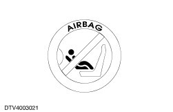
WARNING:All vehicles fitted with the passenger air bag from the factory have a WARNING sticker attached to the instrument panel, PROHIBITING the use of rear facing child or baby seats.
It is not possible under any circumstances to disable the passenger air bag while maintaining the integrity of the whole air bag system.
The air bag system consists of the following components:
- electronic air bag control module
- wiring harness
- air bag sliding contact
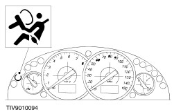
- warning indicator
- air bag module(s)
- side impact crash sensors (when equipped with side air bags)
The electronic air bag control module governs the operation of the whole system, including the diagnostic element. It contains two frontal impact sensors; a crash sensor and a safing sensor. The crash sensor produces a signal corresponding to the rate of deceleration. The safing sensor detects only deceleration. These two sensors are connected in series and if they both sense a deceleration in excess of a predetermined limit, the electronic air bag control module will deploy the air bag module(s).
The electronic air bag control module will also deploy the corresponding side air bag module dependent on the signal received from either crash sensor.
The electronic air bag control module also performs continual system diagnostics. In the event of a fault being detected the warning light is illuminated either constantly or intermittently. The behavior of the warning light depends on the type of fault present. The warning light is located in the instrument cluster.
The wiring harness provides power to the electronic air bag control module from the vehicle supply and hence to the air bag module(s), side impact crash sensors (if equipped with side air bags) and the warning indicator.
The air bag sliding contact is designed to carry signals between the electronic air bag control module and the driver air bag module. The air bag sliding contact is fitted to the steering column multifunction switch mounting bracket, and consists of fixed and moving parts connected by a coiled Mylar tape with integral conducting tracks. The Mylar tape is able to `wind up' and `unwind' as the steering wheel (to which the moving part is attached) is turned, maintaining electrical contact at all times between the electronic air bag control module and the air bag module. The air bag sliding contact is used in order to achieve the high degree of circuit integrity required by such a critical safety system as the supplemental restraint system (SRS).
The driver, passenger and side air bag modules consist of the following components which cannot be disassembled:
- inflator
- bag
- container
- cover
Driver and Passenger air bag module inflator
4
-
Passenger inflator unit
The inflator is screwed into a metal cup - shaped container. The bag is then folded on top of the inflator and the whole subassembly is enclosed by the cover.
The driver air bag module is fitted to the steering wheel, the cover forming the outer surface of the steering wheel boss. The cover has invisible `split lines' moulded in its surfaces allowing the air bag to easily exit through the cover when the system deploys.
The passenger air bag module is located above the glove compartment and is integrated into the instrument panel top to provide an unobtrusive appearance. The cover is a one piece moulding, which is attached to the instrument panel along its upper edge, the lower edge is attached to the instrument panel by two plastic retainers. As the air bag deploys, the cover is forced free of the retainers, but remains attached to the instrument pad panel along its upper edge.
The side air bag module(s) are integrated into the front seat backrests providing an unobtrusive appearance. The unique seat cover has been designed to accommodate air bag deployment. When the side air bag is deployed the stitched seam of the seat cover adjacent to the side air bag module splits, allowing the air bag to exit the seat backrest unobstructed.
The purpose of the inflator is to generate the gas needed to fill the air bag. It consists of a high strength steel casing filled with a solid propellant charge and an electrically activated igniter. The igniter is activated by a signal from the electronic control module which in turn ignites the propellant charge. The very rapid burning of the propellant produces sufficient gas to fill the air bag(s). As the gases expand they cool, preventing heat damage to the bag. The drivers air bag module has one inflator and bag, with a filled volume of 55 litres. The passenger air bag module has two inflators and bag having a filled volume of 60 litres. The side air bag has a single inflator and a bag with a filled volume of 12 litres.
The bag(s) are a one - piece woven item with a silicon coating to provide flame and heat protection in the vicinity of the inflator. The shape of the passenger and side air bag (when equipped) are tailored to the vehicle proportions.
The supplemental restraint system fitted to the Cougar will communicate faults/concerns by the air bag control module during a driving cycle or after initial key ON by means of a warning indicator contained within the instrument cluster.