| Removal and Installation Special Tool(s) | | Alignment Pins, Subframe 205-316 | | | Wrench, Steering Gear 211-186 | | | Seperator, Ball Joint 211-020 | Removal All Vehicles | | -
Remove both front wheels. | | | -
CAUTION:Do not damage the boot and the ABS-sensor ring Disconnect the lower arm ball joints and the stabilizer bar link rods (use the special tool 211-020) (right-hand side shown). | | | -
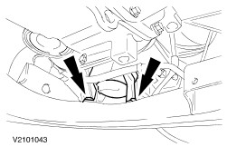
Remove the LH engine support insulator. - Remove the through bolt.
- Remove the nuts.
- Remove the LH support insulator.
| Vehicles with air conditioning | | -
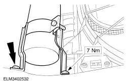
Remove the suction accumulator bracket bolts. | | | -
Remove the radiator splash shield. - Remove the push pins.
- Remove the bolts.
- Remove the radiator splash shield.
| Vehicles with 2.0L engine | | -
Disconnect the exhaust flexible pipe and detach hanger insulator. | Vehicles with 2.5L engine | | -
Disconnect the front exhaust pipe. | Vehicles with 2.5L engine | | -
Disconnect and remove the rear catalytic converter. | | | -
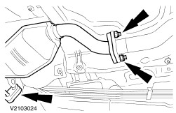
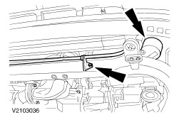
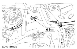
Remove the power steering hose bracket bolt. | | | -
Remove the power steering hose bracket nut. | | | -
Remove the power steering hose bracket bolt. | | | -
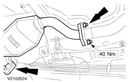
Remove the transaxle cooler line brackets and bolt. - Reposition air conditioner canister, if necessary.
| | | -
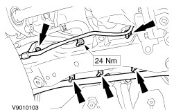
NOTE:Secure the steering gear using mechanics wire before removing the subframe. Remove the steering gear and the RH engine support insulator. - Using the special tool, remove the steering gear from the subframe.
- Remove the support insulator from the bracket.
- Remove the support insulator from the subframe.
| Vehicles with 2.5L engine | | -
Remove the steering gear heat shield. | Vehicles with 2.5L engine | | -
Use the special tool 211-186. Remove the steering gear (two bolts) and tie it up (left-hand side shown). | | | -
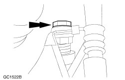
Disconnect the right-hand engine support insulator. | | | -
Disconnect the right-hand engine support insulator. | | | -
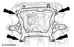
WARNING:Support the subframe using a Powertrain Lift. Remove the subframe bolts and subframe (vehicle with 2.5L engine shown). | Installation All Vehicles | | -
Install the subframe (vehicle with 2.5L engine shown). - Install the special tool.
- Align the subframe with the locating holes in the body.
- Install the subframe bolts working diagonally.
| | | -
Remove the mechanics wire securing the steering gear. | Vehicles with manual transmission | | -
NOTE:Verify that the right-sight support insulator is centered in the bracket and in perfect front to rear alignment before tightening the through bolt. If necessary, loosen the support insulator to subframe mounting bolts and reposition the support insulator. Install the steering gear and the right-hand engine support insulator. - To the subframe.
- To the bracket.
- Using the special tool, install the steering gear bolts.
| | | -
Use the special tool 211-186. Install the steering gear (two bolts) (left-hand side shown). | | | -
Install the right-hand engine support insulator. | Vehicles with 2.5L engine | | -
Install the steering gear heat shield. | | | -
NOTE:Verify that the left-hand support insulator is centered in the transaxle bracket and in perfect front to rear alignment before tightening the through bolt. Install the LH engine support insulator. - Position the front support insulator.
- Install the nuts.
- Install the through bolt.
| | | -
NOTE:Powertrain neutralising process should be applied if insulators cannot be centraliced within given slots. | | | -
Install the transaxle cooler line brackets and bolt. | | | -
Install the power steering hose bracket bolt. | | | -
Attach the power steering hose to the subframe. | | | -
Install the power steering hose bracket bolt. | Vehicles with 2.0L engine | | -
Connect the exhaust flexible pipe. | Vehicles with 2.5L engine | | -
Connect the rear catalytic converter. | Vehicles with 2.5L engine | | -
CAUTION:Don't use jointing compound in front of catalytic converters. Connect the front exhaust pipe. | | | -
Install the radiator splash shield. - Position the radiator splash shield.
- Install the bolts.
- Install the push pins.
| Vehicles with air conditioning | | -
Install the suction accumulator bolts to the subframe. | | | -
CAUTION:Do not damage the boot and the ABS-sensor ring Connect the lower arm ball joints and the stabilzer bar link rods. | | | -
Install the front wheels. | | | -
Remove the radiator supports. | | | -
Tighten the front wheels (right-hand side shown). | |