
Crown Victoria V8-4.6L SOHC VIN 6 (1996)
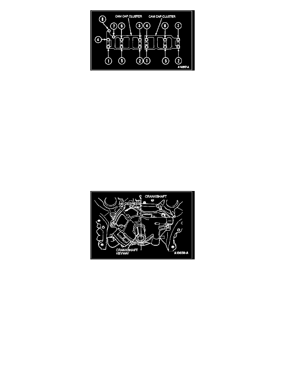
4. Tighten camshaft cap cluster retaining bolts in sequence to 8-12 N-m (6.0-8.8 lb-ft).
5. Loosen 14 camshaft cap cluster retaining bolts approximately two turns or until head of bolt is free.
NOTE: Camshaft should turn freely with a slight drag.
6. Retighten all bolts in sequence to 8-12 N-m (6.0-8.8 lb-ft).
7. Check camshaft end play using Rotunda Dial Indicator with Bracketry 014-00282 or equivalent.
8. If necessary, install Cam Positioning Tool T92P-6256-A on flats of camshaft and install spacer and camshaft gear. Install bolt and washer and
tighten to 110-130 N-m (81-95 lb-ft).
NOTE: Valve Spring Spacer T91P-6565-AH must be installed between spring coils and the camshaft must be at base circle prior to compressing
valve spring. Rotate camshaft as necessary until all roller followers are installed.
9. Install Valve Spring Compressor T91P-6565-A, under camshaft and on top of valve spring retainer. Install lash adjusters.
10. Compress valve spring far enough to install roller follower.
11. Repeat Steps 8 and 9 until all roller followers are installed. Remove Valve Spring Spacer from coil springs.
NOTE: Steps 2 through 11 will install only one camshaft. If both camshafts are being serviced, repeat Steps 2 through 11 to install the other
camshaft.
CAUTION: Crankshaft must only be rotated in the clockwise direction and only as far as TDC.
12. Rotate crankshaft clockwise 45 degrees.
NOTE: This will position crankshaft at TDC.
CAUTION: Timing chain procedures must be followed exactly or damage to valves and/or pistons will result.
13. Install timing chains as outlined.
14. Inspect and replace front cover seal and gasket.