
F 150 4WD V8-4.6L VIN 8 (2010)
-------------------------------------------------
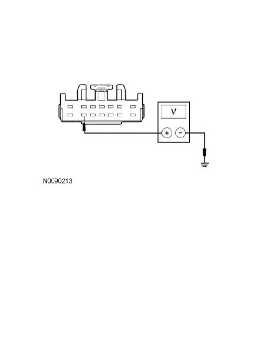
G1 CHECK THE TBC MODULE VOLTAGE SUPPLY CIRCUIT FOR AN OPEN
-
Ignition OFF.
-
Disconnect: TBC Module C2142.
-
Ignition ON.
-
Measure the voltage between the TBC module C2142-8, circuit SBB17 (RD) or VB-A (GY/RD), harness side and ground.
-
Is the voltage greater than 10 volts?
Yes
GO to G2.
No
VERIFY the Battery Junction Box (BJB) fuse 17 (30A) is OK. If OK, REPAIR the circuit. If not OK, REFER to the Wiring Diagrams to identify the
possible causes of the circuit short. CLEAR the DTCs. REPEAT the network test with the scan tool. See: Diagrams/Electrical Diagrams/Diagrams By
Number
-------------------------------------------------
G2 CHECK THE TBC MODULE GROUND CIRCUIT FOR AN OPEN
-
Ignition OFF.
-
Disconnect: Negative Battery Cable.
-
Measure the resistance between the TBC module C2142-3, circuit GD138 (BK/WH) or GND-A (BK/GY), harness side and ground.