
F 250 2WD Pickup V8-7.3L DSL (1990)
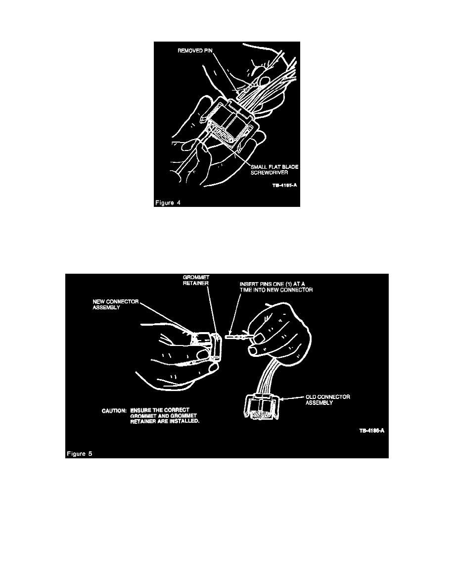
THE TERMINAL AND WIRE ASSEMBLIES MUST BE REMOVED FROM THE OLD CONNECTOR AND INSERTED INTO THE NEW
CONNECTOR ONE (1) WIRE AT A TIME.
2.
Using a small, thin flat-bladed screwdriver or equivalent, gently insert down into the connector body and release the "locking finger" for the
connector terminal. At the same time, grasp the wire and gently pull the terminal/wire assembly through the back of the connector (Figure 4).
CAUTION:
ENSURE PROPER GROMMET IS USED. THERE MUST NOT BE ANY OPEN TERMINAL/WIRE LOCATIONS LEFT IN THE GROMMET.
REMEMBER TO REINSTALL THE GROMMET RETAINER WHEN CHANGING THE GROMMET.
3.
If necessary, remove the grommet retainer and install the correct grommet, then reinstall the grommet retainer. Insert the terminal/wire assembly
through the grommet retainer and grommet, then into the correct location (Figure 5) of the connector. The terminal/wire assembly can only be
inserted into the connector in one (1) direction. Ensure each assembly is properly seated in the new connector. A "snap" should be felt and heard.
CAUTION:
ENSURE TERMINAL/WIRE ASSEMBLIES ARE INSERTED INTO THEIR CORRECT LOCATIONS AND THE PROPER GROMMET IS
BEING USED. REFER TO THE APPROPRIATE SERVICE MANUAL FOR PIN OUT, IF REQUIRED.
4.
Repeat Steps 2 and 3 for the remaining terminal/wire assemblies.
5.
Install the "red" pin spacer plate from the kit by snapping it into the new connector.