| Removal and Installation Special Tool(s) | | Installer, Halfshaft 204-161 (14-041) | | | Clamping Tool, Boot Retaining Clamp 204-169 (14-044) | General Equipment Snap-ring pliers Clamping straps Two leg puller Materials Name Specification High-durability grease WSD-M1C230-A Removal | | -
Loosen the axle stub nut. | | | -
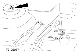
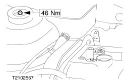
NOTE:Use an Allen key to stop the piston rod from turning. Loosen the suspension strut top nut by five turns. | | | -
Raise the vehicle. - Detach the lower suspension arm from the spindle carrier.
| | | -
Release the clamping straps from the boot. - Slide the boot onto the front drive halfshaft.
| | | -
CAUTION:The inner constant velocity (CV) joint must not be bent more than 18 degrees, and the outer joint more than 45 degrees. CAUTION:Carefully push the wheel suspension outwards to avoid damage to the tripod joint (inner joint). Detach the front drive halfshaft from the halfshaft joint. - Pull off the boot and tie up the front drive halfshaft.
- Remove the grease from inside the joint.
- Open the snap-ring using snap-ring pliers and hold it open.
| | | -
CAUTION:The axle stub nut can be reused four times. Mark the nut. CAUTION:Support the axle stub. Unscrew and remove the axle stub nut and remove the washer. | | | -
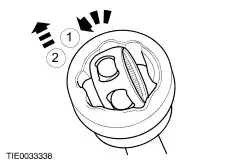
Disassemble the outer CV joint ball bearing cage together with the outer CV joint inner race from the outer CV joint housing. - Turn the cage together with the inner race.
- Pull off the cage together with the inner race.
| | | -
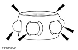
Remove the outer CV joint bearing balls. | | | -
NOTE:Make sure that the outer CV joint housing, the outer CV joint inner race, the outer CV joint bearing balls and the outer CV joint ball bearing cage are free of oil and grease. Check all mating faces for abrasion. | Installation | | -
General note. - Renew all snap-rings and clamping straps.
| | | -
Install the outer constant velocity (CV) joint bearing balls. | | | -
Assemble the outer CV joint ball bearing cage together with the outer CV joint inner race to the outer CV joint housing. - Insert the cage together with the inner race.
- Turn the cage together with the inner race.
| | | -
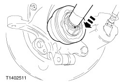
CAUTION:The axle stub nut can be reused four times; mark the nut. Pull the axle stub into the wheel hub using the special tool. - Insert the washer and screw on the axle stub nut.
| | | -
CAUTION:Do not bend the inner CV joint more than 18 degrees and the outer CV joint more than 45 degrees. NOTE:Make sure the snap-ring snaps securely into place. Install the front drive halfshaft. - Slide the boot onto the front drive halfshaft.
- Insert a new snap-ring into the drive halfshaft joint groove.
- Insert the front drive halfshaft into the halfshaft joint until the snap-ring engages.
| | | -
- Fill level for models with Endura-DE diesel engines: 40g on each side.
- Capacity for all other models: 30g on each side.
| | | -
Make a clamp head for Special Tool 204-169. - Material: aluminium or steel plate.
| | | -
Position the halfshaft joint boot and secure it using new clamping straps. - Insert the clamp head in the special tool.
- Apply the special tool so that the clamp head is vertical to the clamping strap head.
| | | -
Attach the lower suspension arms to the spindle carriers. | | | -
NOTE:Use an Allen key to stop the piston rod from turning. Tighten the suspension strut top nut. | | | -
Tighten the axle stub nut. | | |