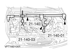
| Removal Special Tool(s) | | Extractor pin, drive shaft 16-087 | | | Remover, front axle driveshaft 16-089 | | | Engine support bar 21-140 | | | Adapter for 21-140 21-140-01 | | | Adapter for 21-140 21-140-03 | Materials Name Specification Transmission fluid WSD-M2C200-C Removal All Vehicles | | -
General note. - The position descriptions for the engine mountings and the engine roll restrictor are given looking from the transmission towards the engine.
| | | -
Preparatory operations - Make a note of the radio keycode.
- Make a note of the preset radio stations.
| | | -
Disconnect the battery ground lead. | | | -
NOTE:Use an Allen key to stop the piston rod from turning. On each side loosen the suspension strut top nut five turns. | | | -
Remove the air intake pipe. | | | -
Remove the battery. - Disconnect the battery positive lead.
- Remove the retaining clip.
- Unclip the wiring brackets.
| | | -
Disconnect the plug of the heated exhaust gas oxygen sensor (HO2S). | | | -
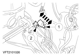
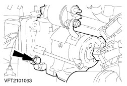
Disconnect the starter motor solenoid switch plug. - Solenoid switch plug
- Unclip the wiring bracket.
| | | -
Disconnect the ground lead from the transmission. | | | -
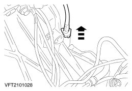
Disconnect the speedometer drive cable. | | | -
Disconnect the vehicle speed sensor (VSS) connector. | | | -
- Undo the quick-release couplings.
| | | -
NOTE:Watch out for escaping brake fluid. Observe the safety precautions when dealing with brake fluid. Push the pipe out of the bracket. - Pull out the securing clip and disconnect the pipe.
- Close off the openings with suitable plugs.
| | | -
Attach the engine lifting eyes. - Attach the engine lifting eye using the exhaust manifold nut (cylinder no. 4).
- Engine lifting eye Finis Code: 6009618
| | | -
Attach the engine lifting eyes (continued). | | | -
Attach engine lifting eyes (continued). - Engine lifting eye Finis Code: 6630411
| | | -
Attach the special tools (continued) | | | -
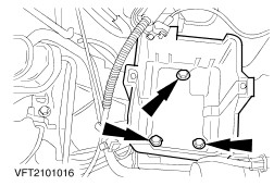
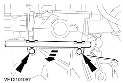
Remove the rear engine mounting (three nuts). - Pull out the transmission breather.
| | | -
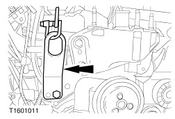
NOTE:The drive belt cover must be removed as it would otherwise be destroyed when the engine is lowered. Remove the drive belt cover. | | | -
Disconnect the plug of the multi-function switch. | | | -
CAUTION:The flexible pipe can be damaged if it is bent too far. Support the flexible pipe with a suitable protective boot. | | | -
Separate the exhaust system. | | | -
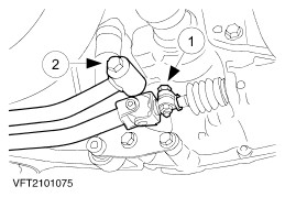
Detach the shift rod and the gearshift stabilizer from the transmission. - Shift rod
- Detach the gearshift stabilizer and tie it up.
| | | -
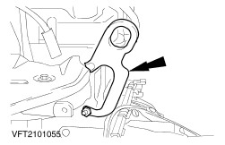
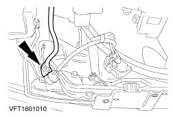
Remove the engine roll restrictor. | | | -
Detach the exhaust pipe and exhaust pipe bracket. | | | -
Detach the left and right suspension arms from the spindle carriers (left-hand side shown). | | | -
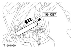
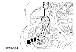
CAUTION:The inner joint must not be bent at more than 18 degrees and the outer joint must not be bent at more than 45 degrees. NOTE:Escaping oil. Close off the transmission with auxiliary plugs. Push the left-hand front driveshaft out of the transmission, pivot it backwards and tie it up. | | | -
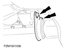
Release the front driveshaft centre bearing. | Vehicles with a two-part intermediate shaft | | -
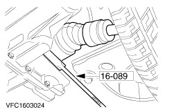
CAUTION:The inner joint must not be bent at more than 18 degrees and the outer joint must not be bent at more than 45 degrees. Remove the right-hand front driveshaft from the transmission. | Vehicles with a one-part intermediate shaft | | -
CAUTION:The inner joint must not be bent at more than 18 degrees and the outer joint must not be bent at more than 45 degrees. CAUTION:After removing the front driveshaft, immediately prevent the differential turning with a suitable assembly stop. Pull the right-hand front axle driveshaft out of the transmission | | | -
CAUTION:The inner joint must not be bent at more than 18 degrees and the outer joint must not be bent at more than 45 degrees. NOTE:Do not damage the boots of the drive shaft. Tie up the right-hand front axle driveshaft towards the front. | | | -
NOTE:Lower the transmission only until the transmission can be removed. Lower the transmission with the engine support bar to the level of the side member. | | | -
Disconnect the starter motor. | | | -
Disconnect the starter motor (continued). - Remove the retaining plate.
- Tie up the starter motor.
| | | -
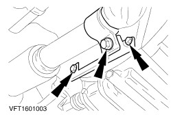
Remove the flange bolts on the right-hand side. | | | -
Remove the flange bolts at the top. - Place the cable guide to one side.
- Remove the adapter plate.
| | | -
Remove the flange bolts at the left-hand side. - Lay the crankshaft position sensor (CKP sensor) cover to one side.
| | | -
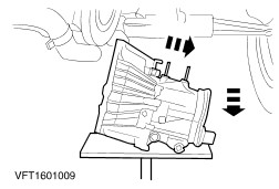
NOTE:Make sure the transmission is seated securely on the transmission jack. Separate the transmission from the engine and lower it. | |