| Removal Special Tool(s) | | Extractor pin, drive halfshaft 308-237 (16-087) | | | Extractor, drive halfshaft (left-hand side) 308-256 (16-089) | | | Engine support bar 303-290 (21-140) | | | Adapter for 21-140 303-290-01 (21-140-01) | | | Adapter for 21-140 303-290-03 (21-140-03) | General Equipment Materials Name Specification Transmission fluid WSD-M2C200-C Removal All Vehicles | | -
General note. - The position descriptions for the engine mountings and the engine roll restrictor are given looking from the transmission towards the engine.
| | | -
Preparatory operations - Make a note of the radio keycode.
- Make a note of the preset radio stations.
| | | -
NOTE:Use an Allen key to stop the piston rod from turning. On each side loosen the suspension strut top nut five turns. | | | -
Detach the air intake pipe. - Detach it from the inlet manifold (clip).
- Release it from its clip.
- Pull it out of the air cleaner housing (push-fit).
- Disconnect it from the resonator hose (clip).
| | | -
WARNING:Brake fluid contains polyglycol ether and polyglycol. Prevent eye contact. Wash your hands thoroughly after working with brake fluid. If brake fluid gets into the eyes, flush the eyes with cold running water for 15 minutes. If the irritation persists, call a doctor. If brake fluid is swallowed, drink water and induce vomiting. Call a doctor immediately. Failure to observe these instructions can lead to personal injury. CAUTION:If brake fluid contacts the paintwork, rinse the affected areas immediately with cold water. Detach the hydraulic pipe of the clutch operating system. - Pull out the securing clip and disconnect the pipe.
- Seal the opening with a suitable plug.
| | | -
NOTE:The bracket of the catalyst is secured with a bolt. Remove the upper transmission flange bolts. | | | -
Fit the special tools. - Slightly raise the engine and transmission assembly.
| | | -
Detach the rear engine mounting from the transmission. - Pull out the transmission breather.
| | | -
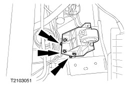
Remove the front engine mounting bracket. | | | -
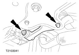
Disconnect the shift rod and the shift rod stabilizer. - Shift rod
- Shift rod stabilizer
| | | -
NOTE:The engine roll restrictor is under tension. Remove the engine roll restrictor. | | | -
Pull off the connector of the multi-function switch (or reversing light switch if necessary) (multi-function switch connector shown). | | | -
Disconnect the speedometer drive cable from the transmission. | | | -
Disconnect the starter motor. - Tie the starter motor up.
| | | -
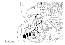
Detach the lower suspension arm from the spindle carrier on each side (left-hand side shown). | Vehicles with a two-part intermediate shaft | | -
Detach the clamping strap. | | | -
CAUTION:The inner joint must not be bent at more than 18 degrees; the outer joint must not be bent at more than 45 degrees. Separate the left-hand front drive halfshaft together with tripode joint from the tripode housing, swing it backwards and tie it up. - Remove the grease from inside the joint.
| | | -
Undo the front drive halfshaft centre bearing. | | | -
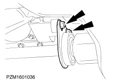
CAUTION:The inner joint must not be bent at more than 18 degrees; the outer joint must not be bent at more than 45 degrees. NOTE:The intermediate shaft extension remains in the transmission. Detach the intermediate shaft from the intermediate shaft extension (shown with the intermediate shaft extension removed). - Undo the clamping straps.
- Slide the boot onto the intermediate shaft.
| Vehicles with a one-part intermediate shaft | | -
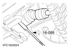
CAUTION:The inner joint must not be bent at more than 18 degrees; the outer joint must not be bent at more than 45 degrees. Press the left-hand front drive halfshaft out of the transmission and suspend it towards the front. - Seal the transmission opening with auxiliary plugs.
| | | -
CAUTION:The inner joint must not be bent at more than 18 degrees; the outer joint must not be bent at more than 45 degrees. Extract the right-hand front drive halfshaft from the transmission. | | | -
CAUTION:The inner joint must not be bent at more than 18 degrees; the outer joint must not be bent at more than 45 degrees. NOTE:Do not damage the boots of the drive halfshaft. Tie up the right-hand front drive halfshaft at the front. | All vehicles | | -
Lower the transmission. - Lower the transmission just far enough with Special Tool 21-140 so that the studs of the engine mounting bracket are accessible.
| | | -
- Support the transmission on a transmission jack.
| | | -
Remove the resonator stud. | | | -
Remove the six flange bolts. - Separate the transmission from the engine and lower it.
| |