| Diagnosis and Testing Refer to Wiring Diagrams Section 417-02, for schematic and connector information. Inspection and Verification – All Vehicles - Verify the customer concern.
- Visually inspect for obvious signs of electrical damage.
Visual Inspection Chart | Electrical | | Fuse(s) | | Wiring harness | | Electrical connector(s) | | Bulb(s) | | Lamp(s) | | Switch(es) | - If an obvious cause for an observed or reported concern is found, correct the cause (if possible) before proceeding to the next step.
- If the concern is not visually evident, verify the symptom and refer to the Symptom Chart.
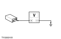
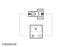
Symptom Chart Symptom Chart | Symptom | Possible Sources | Action | | The interior lamps are inoperative | * Circuit(s). * Interior lamp. * Bulb(s). | * | | The interior lamps stay on continuously | * Interior lamps. | * INSTALL a new interior lamp. Test the lamp for normal operation. | | The interior lamp does not turn on with one door open | * Circuit(s). * Switch(es). | * | | Illuminated entry does not fade-out | * Circuit(s). * Entry illumination delay relay. | * REPLACE the entry illumination delay relay. | | The luggage compartment lamp is inoperative. | * Luggage compartment lamp. * Circuit(s). * Tailgate contact plate switch. * Bulb. | * | Pinpoint Tests NOTE:Use a digital multimeter for all electrical measurements. | PINPOINT TEST A : THE INTERIOR LAMPS ARE INOPERATIVE | | TEST CONDITIONS | DETAILS/RESULTS/ACTIONS | | A1: CHECK CIRCUIT 29-LC7 FOR OPEN | | | 1 Disconnect Interior lamp C27b. | | | 2 Measure the voltage between C27b pin 1, circuit 29-LC7 (OG/BU), harness side and ground. | | | Is the voltage greater than 10 volts? Yes INSTALL a new interior lamp. TEST the system for normal operation. No REPAIR the circuit. TEST the system for normal operation. | | PINPOINT TEST B : THE INTERIOR LAMP DOES NOT TURN ON WITH ONE DOOR OPEN | | TEST CONDITIONS | DETAILS/RESULTS/ACTIONS | | B1: CHECK CIRCUITS 31S-LC29, 31S-LC30, 31S-LC32 AND 31S-LC33 FOR OPEN | | | 1 Disconnect Entry illumination delay relay C76. | | | 2 Disconnect the inoperative door ajar switch electrical connector. - C26 - drivers side door.
- C55 - passenger side door.
- C127 - drivers side rear door.
- C125 - passenger side rear door.
| | | 3 Measure the resistance between the entry illumination delay relay C76, circuit 31S-LC4 (BK/BU), harness side and the inoperative door ajar switch electrical connector. - C26 pin 1, circuit 31S-LC29 (BK/RD).
- C55 pin 1, circuit 31S-LC29 (BK/RD).
- C127 pin 1, circuit 31S-LC32 (BK/OG).
- C125 pin 1, circuit 31S-LC33 (BK/OG).
| | | Is the resistance less than 5 ohms? Yes INSTALL a new door ajar switch. TEST the system for normal operation. No REPAIR the inoperative circuit. TEST the system for normal operation. | | PINPOINT TEST C : THE LUGGAGE COMPARTMENT LAMP IS INOPERATIVE | | TEST CONDITIONS | DETAILS/RESULTS/ACTIONS | | C1: CHECK THE THE LUGGAGE COMPARTMENT LAMP CIRCUIT FOR OPEN | | | 1 Open the tailgate. | | | 2 Disconnect Luggage compartment lamp C70. | | | 3 Measure the voltage between the luggage compartment lamp C70 pin 1, circuit 29-LB25 (OG/BU), harness side and C70 pin 2, circuit 31S-LB26 (BK/OG), harness side. | | | Is the voltage greater than 10 volts? Yes INSTALL a new luggage compartment lamp. TEST the system for normal operation. No | | C2: CHECK THE POWER SUPPLY TO THE LUGGAGE COMPARTMENT LAMP | | | 1 Measure the voltage between the luggage compartment lamp C70 pin 1, circuit 29-LB25 (OG/BU), harness side and ground. | | | Is the voltage greater than 10 volts? Yes No REPAIR circuit 29-LB25 (OG/BU). TEST the system for normal operation. | | C3: CHECK CIRCUIT 31-LB26 (BK) FOR OPEN | | | 1 Disconnect Tailgate contact plate C312c. | | | 2 Measure the resistance between tailgate contact plate C312c pin 2, circuit 31-LB26 (BK), harness side and ground. | | | Is the resistance less than 5 ohms? Yes No REPAIR circuit 31-LB26 (BK). TEST the system for normal operation. | | C4: CHECK CIRCUIT 31S-LB26 (BK/OG) FOR OPEN | | | 1 Measure the resistance between the tailgate contact plate C312c pin 1, circuit 31S-LB26 (BK/OG), and the luggage compartment lamp C70 pin 2, circuit 31S-LB26 (BK/OG), harness side. | | | Is the resistance less than 5 ohms? Yes INSTALL a new tailgate contact plate switch. TEST the system for normal operation. No REPAIR the circuit. TEST the system for normal operation. | |