| PINPOINT TEST C : THE DEFROST SYSTEM IS INOPERATIVE |
NOTE:This symptom also covers the defrost system for the heated exterior mirrors and the heated windshield. If the heated rear window or the heated exterior mirrors do not operate, GO to C1; if the heated windshield does not operate, GO to C13. |
| TEST CONDITIONS | DETAILS/RESULTS/ACTIONS |
| C1: CHECK THE OPERATION OF THE HEATED REAR WINDOW |
| | 1 Ignition switch in position II. |
| | 2 Operate the heated rear window control switch. |
| | Does the heated rear window(s) function correctly? Yes No |
| C2: CHECK THE OPERATION OF THE HEATED EXTERIOR MIRRORS |
| | 1 Operate the heated rear window control switch. |
| | Do the heated exterior mirrors operate correctly? Yes VERIFY the customer concern. No |
| C3: CHECK THE OPERATION OF THE HEATED REAR WINDOW RELAY |
| | 1 Operate the heated rear window control switch. |
| | Does the heated rear window relay click? Yes No |
| C4: CHECK FOR VOLTAGE TO THE HEATED REAR WINDOW |
| | 1 Ignition switch in position 0. |
| | 2 Disconnect Heated Rear Window. |
| | 3 Ignition switch in position II. |
| | 4 Operate the heated rear window control switch. |
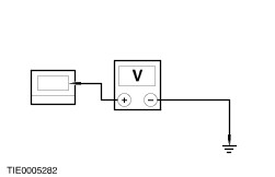
| | 5 Measure the voltage between the heated rear window C218 (C223 or C224 Courier only) harness side and ground. |
| | Is the voltage greater than 10 volts? Yes CARRY OUT the grid wire test. REFER to the procedure in this Section. No REPAIR circuit 14S-HB33 (VT/OG) left rear door or circuit 14S-HB34 (VT/BU) right rear door, Courier only; or circuit 14S-HB19. TEST the system for normal operation. |
| C5: CHECK THE VOLTAGE TO THE INOPERATIVE EXTERIOR MIRROR |
| | 1 Ignition switch in position 0. |
| | 2 Disconnect Inoperative Exterior Mirror. |
| | 3 Ignition switch in position II. |
| | 4 Operate the heated rear window control switch. |
| | 5 Measure the voltage between the inoperative exterior mirror C148 pin 5, circuit 14S-HB35 (VT/BK) driver side; or C147 pin 5, circuit 14S-HB36 (VT/OG) passenger side and ground. |
| | Is the voltage greater than 10 volts? Yes No |
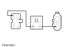
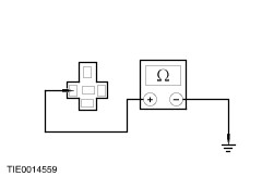
| C6: CHECK THE INOPERATIVE EXTERIOR MIRROR GROUND CIRCUIT |
| | 1 Ignition switch in position 0. |
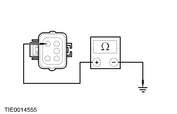
| | 2 Measure the resistance between the inoperative exterior mirror C148 pin 2, circuit 31-HB35 (BK) driver side; or C147 pin 2, circuit 31-HB36 (BK) passenger side and ground. |
| | Is the resistance less than 5 ohms? Yes INSTALL a new exterior mirror. TEST the system for normal operation. No REPAIR circuit 31-HB35 (BK) driver side, or circuit 31-HB36 (BK) passenger side. TEST the system for normal operation. |
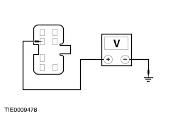
| C7: CHECK FOR VOLTAGE TO THE HEATED REAR WINDOW CONTROL SWITCH |
| | 1 Operate the heated rear window control switch. |
| | Does the ON LED illuminate? Yes No |
| C8: CHECK FOR VOLTAGE TO THE HEATED REAR WINDOW RELAY |
| | 1 Ignition switch in position 0. |
| | 2 Disconnect Heated Rear Window Relay C48. |
| | 3 Ignition switch in position II. |
| | 4 Operate the heated rear window control switch. |
| | 5 Measure the voltage between the heated rear window relay C48 pin 2, harness side and ground. |
| | Is the voltage greater than 10 volts? Yes REPAIR circuit 31-HB21 (BK). TEST the system for normal operation. No REPAIR circuit 14S-HB20 (VT/BK). TEST the system for normal operation. |
| C9: CHECK FOR VOLTAGE TO THE HEATED REAR WINDOW RELAY |
| | 1 Ignition switch in position 0. |
| | 2 Disconnect Heated Rear Window Relay C48. |
| | 3 Ignition switch in position II. |
| | 4 Measure the voltage between the heated rear window relay C48 pin 5, harness side and ground. |
| | Is the voltage greater than 10 volts? Yes No REPAIR circuit 29-HB21 (OG/GN). TEST the system for normal operation. |
| C10: CHECK FOR VOLTAGE TO THE CENTRAL JUNCTION BOX (CJB) FUSE 15 (7.5A) INPUT SIDE |
| | 1 Ignition switch in position 0. |
| | 2 Disconnect Fuse 15 (7.5A). |
| | 3 Ignition switch in position II. |
| | 4 Operate the heated rear window control switch. |
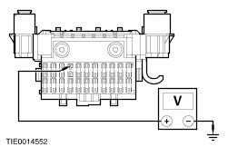
| | 5 Measure the voltage between the CJB fuse 15 (7.5A), input side and ground. |
| | Is the voltage greater than 10 volts? Yes REPAIR circuit 14S-HB35 (VT/BK) driver side, or circuit 14S-HB36 (VT/OG) passenger side. TEST the system for normal operation. No REPAIR circuit 14S-HB16 (VT/OG). TEST the system for normal operation. |
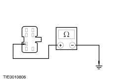
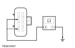
| C11: CHECK FOR CONTINUITY BETWEEN THE HEATED REAR WINDOW CONTROL SWITCH AND GROUND |
| | 1 Ignition switch in position 0. |
| | 2 Disconnect Heated Rear Window Control Switch C60. |
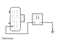
| | 3 Measure the resistance between the heated rear window control switch C60 pin 4, circuit 31-HB22 (BK) harness side and ground. |
| | Is the resistance less than 5 ohms? Yes No REPAIR circuit 31-HB22. TEST the system for normal operation. |
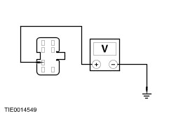
| C12: CHECK THE VOLTAGE BETWEEN THE HEATED REAR WINDOW CONTROL SWITCH AND GROUND |
| | 1 Ignition switch in position II. |
| | 2 Measure the voltage between the heated rear window control switch C60 pin 2, circuit 14-HB22 (VT/BK) harness side and ground. |
| | Is the voltage greater than 10 volts? Yes VERIFY the customer concern. No REPAIR circuit 14-HB22 (VT/BK). TEST the system for normal operation. |
| C13: CHECK OPERATION OF THE HEATED WINDSHIELD RELAY |
| | 1 Ignition switch in position III. |
| | 2 Ignition switch in position II. |
| | 3 Operate the heated windshield switch. |
| | Does the heated windshield relay click? Yes No |
| C14: CHECK FOR VOLTAGE TO THE HEATED WINDSHIELD RELAY |
| | 1 Ignition switch in position 0. |
| | 2 Disconnect Heated Windshield Relay C227. |
| | 3 Ignition switch in position III. |
| | 4 Ignition switch in position II. |
| | 5 Measure the voltage between the heated windshield relay C227 pin 5, harness side and ground. |
| | Is the voltage greater than 10 volts? Yes No REPAIR circuit 30-HB11 (RD). TEST the system for normal operation. |
| C15: CHECK FOR VOLTAGE TO THE HEATED WINDSHIELD GRID WIRES |
| | 1 Ignition switch in position 0. |
| | 2 Connect Heated Windshield Relay C227. |
| | 3 Disconnect C225a/b Heated Windshield Grid Wires. |
| | 4 Ignition switch in position III. |
| | 5 Ignition switch in position II. |
| | 6 Operate the heated windshield control switch. |
| | 7 Measure the voltage between the heated windshield grid wire C225a right-hand side or C225b left-hand side, harness side and ground. |
| | Is the voltage greater than 10 volts? Yes INSTALL a new windshield. TEST the system for normal operation. No REPAIR circuit 14S-HB25 (VT/BU) left-hand side or circuit 14S-HB12 (VT/YE) right-hand side. TEST the system for normal operation. |
| C16: CHECK FOR VOLTAGE TO THE HEATED WINDSHIELD CONTROL SWITCH |
| | 1 Operate the heated windshield control switch. |
| | Does the ON LED illuminate? Yes No |
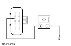
| C17: CHECK FOR CONTINUITY BETWEEN THE HEATED WINDSHIELD RELAY AND GROUND |
| | 1 Ignition switch in position 0. |
| | 2 Disconnect Heated Windshield Relay C227. |
| | 3 Measure the resistance between the heated windshield relay C227 pin 1, circuit 31-HB11 (BK) harness side and ground. |
| | Is the resistance less than 5 ohms? Yes VERIFY the customer concern. No REPAIR circuit 31-HB11 (BK). TEST the system for normal operation. |
| C18: CHECK FOR VOLTAGE TO THE HEATED WINDSHIELD RELAY |
| | 1 Ignition switch in position 0. |
| | 2 Disconnect Heated Windshield Relay C227. |
| | 3 Ignition switch in position III. |
| | 4 Ignition switch in position II. |
| | 5 Operate the heated windshield control switch. |
| | 6 Measure the voltage between the heated windshield relay C227 pin 2 circuit 14S-HB7 (VT/BU), harness side and ground. |
| | Is the voltage greater than 10 volts? Yes No |
| C19: CHECK FOR CONTINUITY BETWEEN THE HEATED WINDSHIELD CONTROL SWITCH AND GROUND |
| | 1 Ignition switch in position 0. |
| | 2 Disconnect Heated Windshield Control Switch C226. |
| | 3 Measure the resistance between the heated windshield control switch C226 pins 2 and 4 circuit 31-HB9 (BK), harness side and ground. |
| | Is the resistance less than 5 ohms? Yes No REPAIR circuit 31-HB6 (BK) or 31-HB9 (BK). TEST the system for normal operation. |
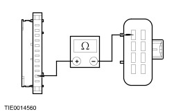
| C20: CHECK FOR CONTINUITY BETWEEN THE HEATED WINDSHIELD CONTROL SWITCH AND THE HEATED WINDSHIELD RELAY |
| | 1 Measure the resistance between the heated windshield control switch C226 pin 6, circuit 14S-HB6 (VT/YE) harness side and the heated windshield relay C227 pin 2, circuit 14S-HB6 (VT/YE) harness side. |
| | Is the resistance less than 5 ohms? Yes VERIFY the customer concern. No REPAIR circuit 14S-HB6 (VT/YE). TEST the system for normal operation. |
| C21: CHECK FOR CONTINUITY BETWEEN THE HEATED WINDSHIELD CONTROL SWITCH AND GROUND |
| | 1 Measure the resistance between the heated windshield control switch C226 pin 2, circuit 31-HB9 (BK) harness side and ground. |
| | Is the resistance less than 5 ohms? Yes No Repair circuit 31-HB9 (BK). TEST the system for normal operation. |
| C22: CHECK FOR CONTINUITY BETWEEN THE HEATED WINDSHIELD CONTROL SWITCH AND THE GENERIC ELECTRONIC MODULE (GEM) |
| | 1 Measure the resistance between the heated windshield control switch C226 pin 1, circuit 31S-HB9 (BK/WH) harness side and the GEM C212a pin 11, circuit 31S-HB9 (BK/WH) harness side. |
| | Is the resistance less than 5 ohms? Yes VERIFY the customer concern. No Repair circuit 31S-HB9 (BK/WH). TEST the system for normal operation. |